HP Pro 4300 Maintenance & Service Guide HP Compaq Pro 4300 All-in-One Busi - Page 60
Webcam Module
 |
View all HP Pro 4300 manuals
Add to My Manuals
Save this manual to your list of manuals |
Page 60 highlights
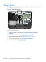
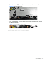
Webcam Module The webcam module is located at the top of the computer beneath the top panel. It is secured with two silver Phillips screws and has one connector. Figure 6-38 Webcam module location To remove the webcam module: 1. Prepare the computer for disassembly (see Preparing to Disassemble the Computer on page 26). 2. Remove the center access panel (see Hinge Cover Panel on page 27). 3. Remove the memory access panel (see Memory Access Panel on page 29). 4. Remove the drive access panel (see Drive Access Panel on page 31). 5. Remove the top panel (see Top Panel on page 51). 52 Chapter 6 Removal and Replacement Procedures All-in One (AIO) Chassis
-
 1
1 -
2
-
3
-
4
-
5
-
6
-
7
-
8
-
9
-
10
-
11
-
12
-
13
-
14
-
15
-
16
-
17
-
18
-
19
-
20
-
21
-
22
-
23
-
24
-
25
-
26
-
27
-
28
-
29
-
30
-
31
-
32
-
33
-
34
-
35
-
36
-
37
-
38
-
39
-
40
-
41
-
42
-
43
-
44
-
45
-
46
-
47
-
48
-
49
-
50
-
51
-
52
-
53
-
54
-
 55
55 -
 56
56 -
 57
57 -
 58
58 -
 59
59 -
 60
60 -
 61
61 -
 62
62 -
 63
63 -
 64
64 -
 65
65 -
66
-
67
-
68
-
69
-
70
-
71
-
72
-
73
-
74
-
75
-
76
-
77
-
78
-
79
-
80
-
81
-
82
-
83
-
84
-
85
-
86
-
87
-
88
-
89
-
90
-
91
-
92
-
93
-
94
-
95
-
96
-
97
-
98
-
99
-
100
-
101
-
102
-
103
-
104
-
105
-
106
-
107
-
108
-
109
-
110
-
111
-
112
-
113
-
114
-
115
-
116
-
117
-
118
-
119
-
120
-
121
-
122
-
123
-
124
-
125
-
126
-
127
-
128
-
129
-
130
-
131
-
132
-
133
 |
 |

Webcam Module
The webcam module is located at the top of the computer beneath the top panel. It is secured with
two silver Phillips screws and has one connector.
Figure 6-38
Webcam module location
To remove the webcam module:
1.
Prepare the computer for disassembly (see
Preparing to Disassemble the Computer
on page
26
).
2.
Remove the center access panel (see
Hinge Cover Panel
on page
27
).
3.
Remove the memory access panel (see
Memory Access Panel
on page
29
).
4.
Remove the drive access panel (see
Drive Access Panel
on page
31
).
5.
Remove the top panel (see
Top Panel
on page
51
).
52
Chapter 6
Removal and Replacement Procedures All-in One (AIO) Chassis