HP Pro 4300 Maintenance & Service Guide HP Compaq Pro 4300 All-in-One Busi - Page 81
Hard Drive and Optical Drive Cables and Connectors,
 |
View all HP Pro 4300 manuals
Add to My Manuals
Save this manual to your list of manuals |
Page 81 highlights
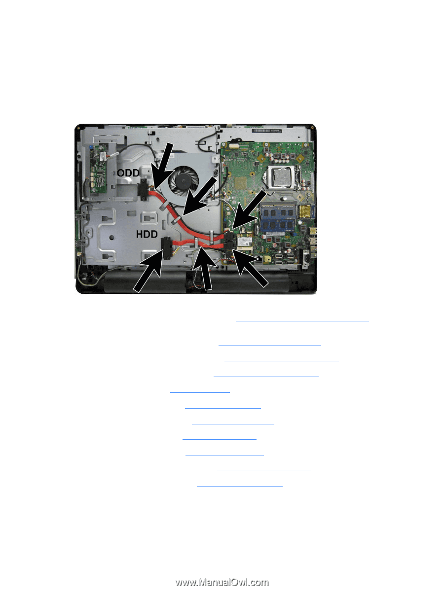
Hard Drive and Optical Drive Cables and Connectors The hard drive and optical drive connectors are located near the middle of the computer, partially under the bracket that secures the stand. Each connector is secured with two Torx screws and has two cables that connect to the system board. The optical drive connector cables are longer than the hard drive connector cables. Figure 6-64 Hard drive cable and optical drive cable location To remove the hard drive or optical drive connector: 1. Prepare the computer for disassembly (see Preparing to Disassemble the Computer on page 26). 2. Remove the center access panel (see Hinge Cover Panel on page 27). 3. Remove the memory access panel (see Memory Access Panel on page 29). 4. Remove the drive access panel (see Drive Access Panel on page 31). 5. Remove the stand (see Stand on page 54). 6. Remove the hard drive (see Hard Drive on page 35). 7. Remove the optical drive (see Optical Drive on page 33). 8. Remove the top panel (see Top Panel on page 51). 9. Remove the rear cover (see Rear Cover on page 55). 10. Remove the system board cover (see Heat Sink Cover on page 45). 11. Remove the stand bracket (see Stand bracket on page 68). 12. Remove two Torx screws that secure the hard drive connector (1) or the optical drive connector (2) to the computer. 13. Remove the cables from the metal clips (3) built into the computer. Hard Drive and Optical Drive Cables and Connectors 73
-
 1
1 -
2
-
3
-
4
-
5
-
6
-
7
-
8
-
9
-
10
-
11
-
12
-
13
-
14
-
15
-
16
-
17
-
18
-
19
-
20
-
21
-
22
-
23
-
24
-
25
-
26
-
27
-
28
-
29
-
30
-
31
-
32
-
33
-
34
-
35
-
36
-
37
-
38
-
39
-
40
-
41
-
42
-
43
-
44
-
45
-
46
-
47
-
48
-
49
-
50
-
51
-
52
-
53
-
54
-
55
-
56
-
57
-
58
-
59
-
60
-
61
-
62
-
63
-
64
-
65
-
66
-
67
-
68
-
69
-
70
-
71
-
72
-
73
-
74
-
75
-
 76
76 -
 77
77 -
 78
78 -
 79
79 -
 80
80 -
 81
81 -
 82
82 -
 83
83 -
 84
84 -
 85
85 -
 86
86 -
87
-
88
-
89
-
90
-
91
-
92
-
93
-
94
-
95
-
96
-
97
-
98
-
99
-
100
-
101
-
102
-
103
-
104
-
105
-
106
-
107
-
108
-
109
-
110
-
111
-
112
-
113
-
114
-
115
-
116
-
117
-
118
-
119
-
120
-
121
-
122
-
123
-
124
-
125
-
126
-
127
-
128
-
129
-
130
-
131
-
132
-
133
 |
 |