HP Pro 4300 Maintenance & Service Guide HP Compaq Pro 4300 All-in-One Busi - Page 66
Converter Board, Preparing to Disassemble the Computer, on Hinge Cover Panel
 |
View all HP Pro 4300 manuals
Add to My Manuals
Save this manual to your list of manuals |
Page 66 highlights
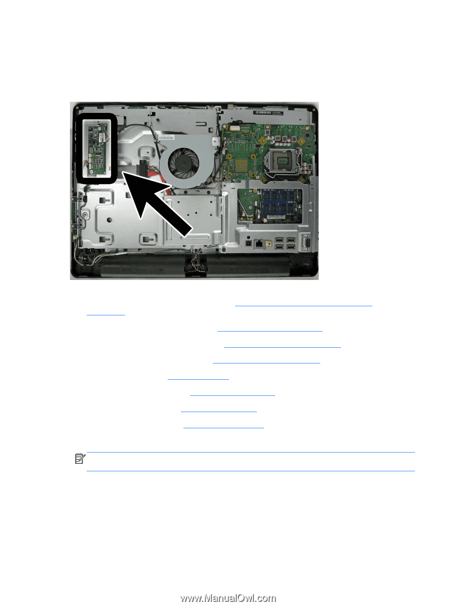
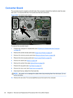
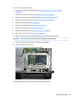
Converter Board The converter board is located on the left side of the computer (viewed from behind) under the main rear cover. It is secured with two Torx screws and has two connectors. Figure 6-46 Converter board location To remove the converter board: 1. Prepare the computer for disassembly (see Preparing to Disassemble the Computer on page 26). 2. Remove the center access panel (see Hinge Cover Panel on page 27). 3. Remove the memory access panel (see Memory Access Panel on page 29). 4. Remove the drive access panel (see Drive Access Panel on page 31). 5. Remove the stand (see Stand on page 54). 6. Remove the optical drive (see Optical Drive on page 33). 7. Remove the top panel (see Top Panel on page 51). 8. Remove the rear cover (see Rear Cover on page 55). 9. Disconnect the two cables from the board (1). NOTE: Be careful not to damage the cables when disconnecting them from the board. Do not pull on the wires. 10. Remove the two silver Torx screws (2) that secure the board to the computer. 58 Chapter 6 Removal and Replacement Procedures All-in One (AIO) Chassis
-
 1
1 -
2
-
3
-
4
-
5
-
6
-
7
-
8
-
9
-
10
-
11
-
12
-
13
-
14
-
15
-
16
-
17
-
18
-
19
-
20
-
21
-
22
-
23
-
24
-
25
-
26
-
27
-
28
-
29
-
30
-
31
-
32
-
33
-
34
-
35
-
36
-
37
-
38
-
39
-
40
-
41
-
42
-
43
-
44
-
45
-
46
-
47
-
48
-
49
-
50
-
51
-
52
-
53
-
54
-
55
-
56
-
57
-
58
-
59
-
60
-
 61
61 -
 62
62 -
 63
63 -
 64
64 -
 65
65 -
 66
66 -
 67
67 -
 68
68 -
 69
69 -
 70
70 -
 71
71 -
72
-
73
-
74
-
75
-
76
-
77
-
78
-
79
-
80
-
81
-
82
-
83
-
84
-
85
-
86
-
87
-
88
-
89
-
90
-
91
-
92
-
93
-
94
-
95
-
96
-
97
-
98
-
99
-
100
-
101
-
102
-
103
-
104
-
105
-
106
-
107
-
108
-
109
-
110
-
111
-
112
-
113
-
114
-
115
-
116
-
117
-
118
-
119
-
120
-
121
-
122
-
123
-
124
-
125
-
126
-
127
-
128
-
129
-
130
-
131
-
132
-
133
 |
 |