HP Pro 4300 Maintenance & Service Guide HP Compaq Pro 4300 All-in-One Busi - Page 90
Power Switch Assembly
 |
View all HP Pro 4300 manuals
Add to My Manuals
Save this manual to your list of manuals |
Page 90 highlights
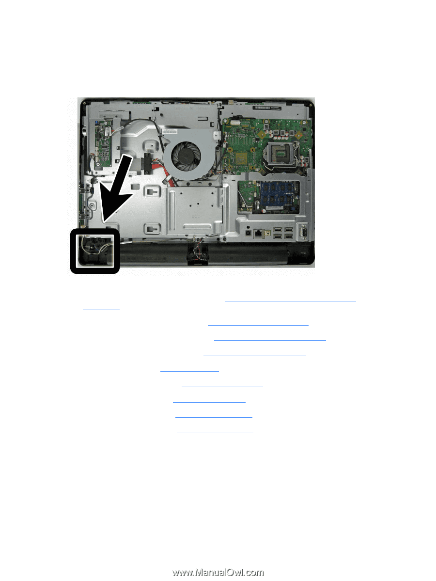
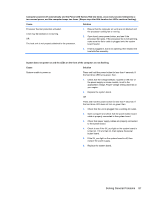
Power Switch Assembly The power switch assembly is located on the bottom corner of the inside of the front bezel. You must remove the front bezel from the computer to remove the power switch assembly from the bezel. Figure 6-72 Power switch assembly location To remove the power switch assembly: 1. Prepare the computer for disassembly (see Preparing to Disassemble the Computer on page 26). 2. Remove the center access panel (see Hinge Cover Panel on page 27). 3. Remove the memory access panel (see Memory Access Panel on page 29). 4. Remove the drive access panel (see Drive Access Panel on page 31). 5. Remove the stand (see Stand on page 54). 6. Remove the optical drive (see Optical Drive on page 33). 7. Remove the top panel (see Top Panel on page 51). 8. Remove the rear cover (see Rear Cover on page 55). 9. Remove the front bezel (see Front Bezel on page 77. 10. Pull the two tabs (1) toward the bottom of the bezel, and then rotate the assembly up and off the bezel (2). 11. Pull the light pipe out of its slot (3). 82 Chapter 6 Removal and Replacement Procedures All-in One (AIO) Chassis
-
 1
1 -
2
-
3
-
4
-
5
-
6
-
7
-
8
-
9
-
10
-
11
-
12
-
13
-
14
-
15
-
16
-
17
-
18
-
19
-
20
-
21
-
22
-
23
-
24
-
25
-
26
-
27
-
28
-
29
-
30
-
31
-
32
-
33
-
34
-
35
-
36
-
37
-
38
-
39
-
40
-
41
-
42
-
43
-
44
-
45
-
46
-
47
-
48
-
49
-
50
-
51
-
52
-
53
-
54
-
55
-
56
-
57
-
58
-
59
-
60
-
61
-
62
-
63
-
64
-
65
-
66
-
67
-
68
-
69
-
70
-
71
-
72
-
73
-
74
-
75
-
76
-
77
-
78
-
79
-
80
-
81
-
82
-
83
-
84
-
 85
85 -
 86
86 -
 87
87 -
 88
88 -
 89
89 -
 90
90 -
 91
91 -
 92
92 -
 93
93 -
 94
94 -
 95
95 -
96
-
97
-
98
-
99
-
100
-
101
-
102
-
103
-
104
-
105
-
106
-
107
-
108
-
109
-
110
-
111
-
112
-
113
-
114
-
115
-
116
-
117
-
118
-
119
-
120
-
121
-
122
-
123
-
124
-
125
-
126
-
127
-
128
-
129
-
130
-
131
-
132
-
133
 |
 |