HP Pro 4300 Maintenance & Service Guide HP Compaq Pro 4300 All-in-One Busi - Page 88
CAUTION, as follows
 |
View all HP Pro 4300 manuals
Add to My Manuals
Save this manual to your list of manuals |
Page 88 highlights
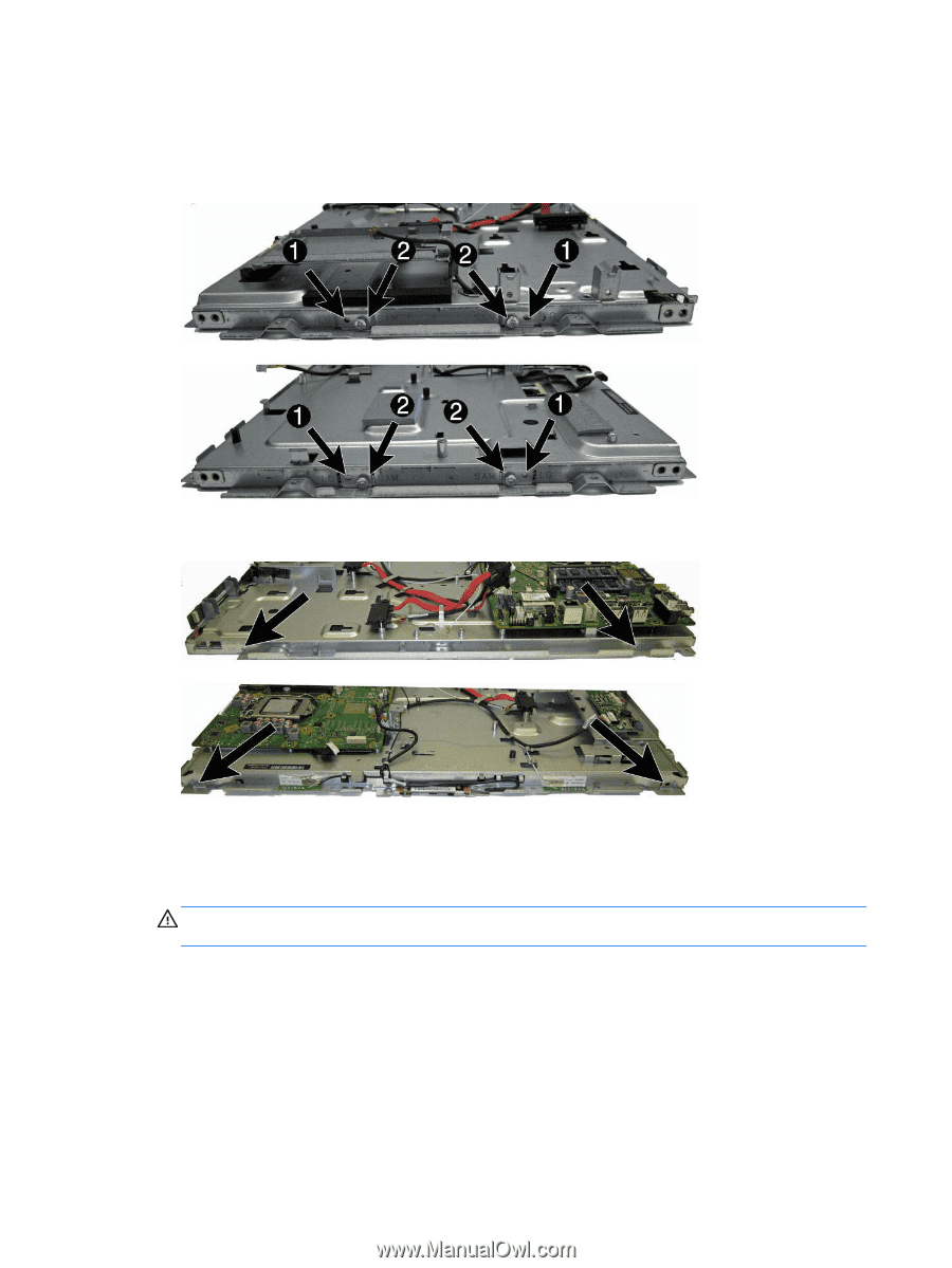
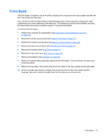
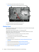
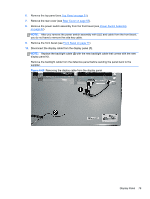
11. Remove the four silver Torx screws that secure the display panel to the frame. The screw locations for each manufacturer are stamped into the metal. The LG (1) and Samsung (2) panels are secured with two screws on each side (left and right). Figure 6-70 Display panel screw locations - LG or Samsung panels The CMI panel is secured with two screws on top, two screws on the bottom. Figure 6-71 Display panel screw locations - CMI panel 12. Lift the display panel from the frame. 13. Be sure to correctly position the jumpers on the converter board for the installed display panel, as follows: CAUTION: Incorrect jumper placement can result in damage to the converter board and LCD panel. ● LG panel: pins (1)(2) & (3)(4) ● Samsung panel: pins (3)(4) & (5)(6) ● CMI panel: pins (1)(2) & (5)(6) 80 Chapter 6 Removal and Replacement Procedures All-in One (AIO) Chassis
-
 1
1 -
2
-
3
-
4
-
5
-
6
-
7
-
8
-
9
-
10
-
11
-
12
-
13
-
14
-
15
-
16
-
17
-
18
-
19
-
20
-
21
-
22
-
23
-
24
-
25
-
26
-
27
-
28
-
29
-
30
-
31
-
32
-
33
-
34
-
35
-
36
-
37
-
38
-
39
-
40
-
41
-
42
-
43
-
44
-
45
-
46
-
47
-
48
-
49
-
50
-
51
-
52
-
53
-
54
-
55
-
56
-
57
-
58
-
59
-
60
-
61
-
62
-
63
-
64
-
65
-
66
-
67
-
68
-
69
-
70
-
71
-
72
-
73
-
74
-
75
-
76
-
77
-
78
-
79
-
80
-
81
-
82
-
 83
83 -
 84
84 -
 85
85 -
 86
86 -
 87
87 -
 88
88 -
 89
89 -
 90
90 -
 91
91 -
 92
92 -
 93
93 -
94
-
95
-
96
-
97
-
98
-
99
-
100
-
101
-
102
-
103
-
104
-
105
-
106
-
107
-
108
-
109
-
110
-
111
-
112
-
113
-
114
-
115
-
116
-
117
-
118
-
119
-
120
-
121
-
122
-
123
-
124
-
125
-
126
-
127
-
128
-
129
-
130
-
131
-
132
-
133
 |
 |