HP Pro 4300 Maintenance & Service Guide HP Compaq Pro 4300 All-in-One Busi - Page 87
Top Panel, on Rear Cover, Power Switch Assembly, Front Bezel,
 |
View all HP Pro 4300 manuals
Add to My Manuals
Save this manual to your list of manuals |
Page 87 highlights
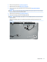
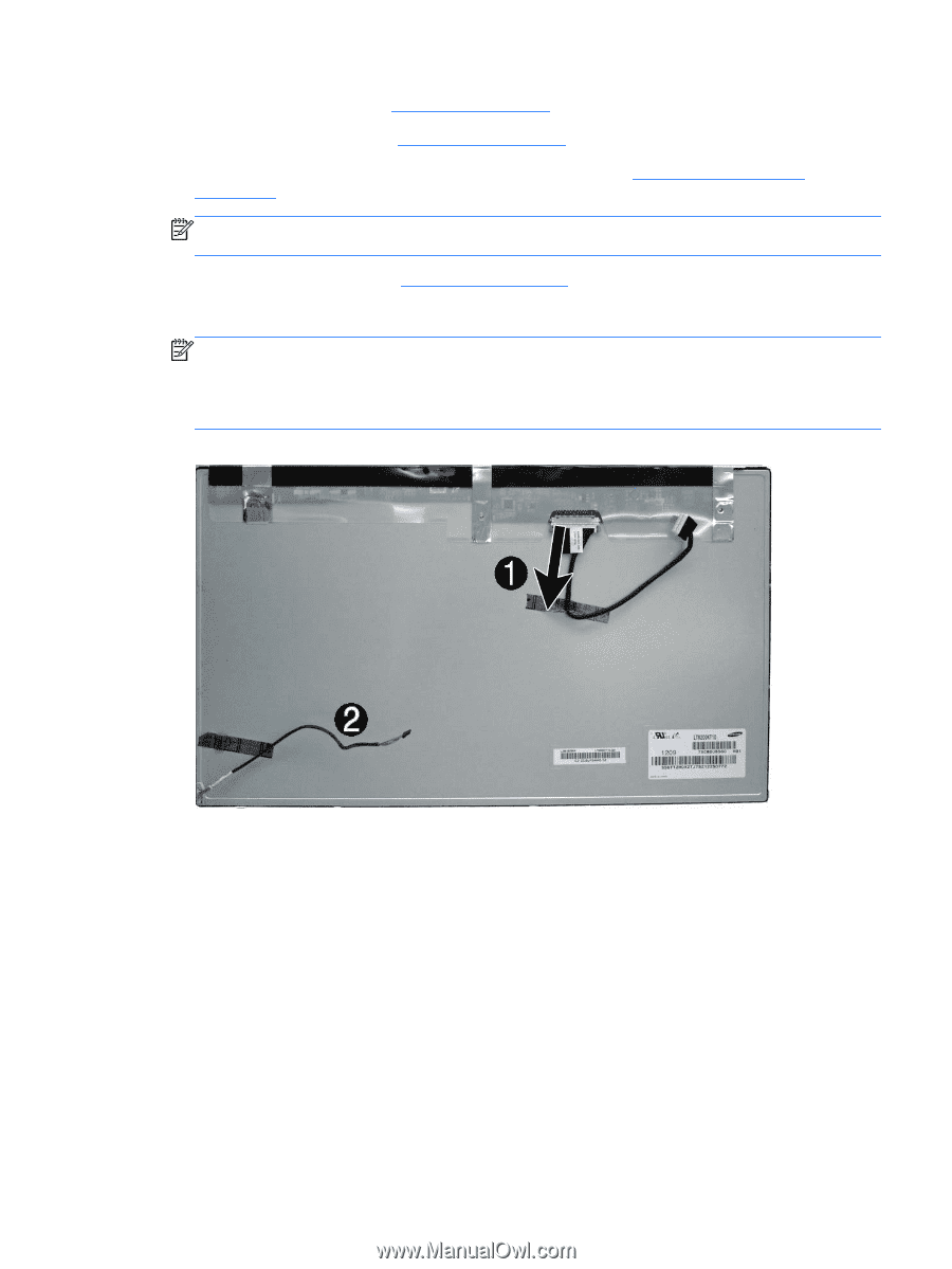
6. Remove the top panel (see Top Panel on page 51). 7. Remove the rear cover (see Rear Cover on page 55). 8. Remove the power switch assembly from the front bezel (see Power Switch Assembly on page 82). NOTE: After you remove the power switch assembly with LED and cable from the front bezel, you do not have to remove the side key cable. 9. Remove the front bezel (see Front Bezel on page 77). 10. Disconnect the display cable from the display panel (1). NOTE: Replace the backlight cable (2) with the new backlight cable that comes with the new display panel kit. Remove the backlight cable from the defective panel before sending the panel back to the supplier. Figure 6-69 Removing the display cable from the display panel Display Panel 79
-
 1
1 -
2
-
3
-
4
-
5
-
6
-
7
-
8
-
9
-
10
-
11
-
12
-
13
-
14
-
15
-
16
-
17
-
18
-
19
-
20
-
21
-
22
-
23
-
24
-
25
-
26
-
27
-
28
-
29
-
30
-
31
-
32
-
33
-
34
-
35
-
36
-
37
-
38
-
39
-
40
-
41
-
42
-
43
-
44
-
45
-
46
-
47
-
48
-
49
-
50
-
51
-
52
-
53
-
54
-
55
-
56
-
57
-
58
-
59
-
60
-
61
-
62
-
63
-
64
-
65
-
66
-
67
-
68
-
69
-
70
-
71
-
72
-
73
-
74
-
75
-
76
-
77
-
78
-
79
-
80
-
81
-
 82
82 -
 83
83 -
 84
84 -
 85
85 -
 86
86 -
 87
87 -
 88
88 -
 89
89 -
 90
90 -
 91
91 -
 92
92 -
93
-
94
-
95
-
96
-
97
-
98
-
99
-
100
-
101
-
102
-
103
-
104
-
105
-
106
-
107
-
108
-
109
-
110
-
111
-
112
-
113
-
114
-
115
-
116
-
117
-
118
-
119
-
120
-
121
-
122
-
123
-
124
-
125
-
126
-
127
-
128
-
129
-
130
-
131
-
132
-
133
 |
 |
6.
Remove the top panel (see
Top Panel
on page
51
).
7.
Remove the rear cover (see
Rear Cover
on page
55
).
8.
Remove the power switch assembly from the front bezel (see
Power Switch Assembly
on page
82
).
NOTE:
After you remove the power switch assembly with LED and cable from the front bezel,
you do not have to remove the side key cable.
9.
Remove the front bezel (see
Front Bezel
on page
77
).
10.
Disconnect the display cable from the display panel
(1)
.
NOTE:
Replace the backlight cable
(2)
with the new backlight cable that comes with the new
display panel kit.
Remove the backlight cable from the defective panel before sending the panel back to the
supplier.
Figure 6-69
Removing the display cable from the display panel
Display Panel
79