HP Pro 4300 Maintenance & Service Guide HP Compaq Pro 4300 All-in-One Busi - Page 78
System Board
 |
View all HP Pro 4300 manuals
Add to My Manuals
Save this manual to your list of manuals |
Page 78 highlights
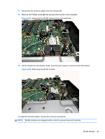
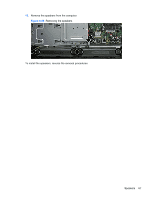
System Board The system board is located on the right side of the computer (viewed from the rear) under the heat sink and system board covers. It is secured with eight Torx screws. Figure 6-62 System board location To remove the system board: 1. Prepare the computer for disassembly (see Preparing to Disassemble the Computer on page 26). 2. Remove the center access panel (see Hinge Cover Panel on page 27). 3. Remove the memory access panel (see Memory Access Panel on page 29). 4. Remove the memory modules (see Memory on page 38). 5. Remove the drive access panel (see Drive Access Panel on page 31). 6. Remove the stand (see Stand on page 54). 7. Remove the optical drive (see Optical Drive on page 33). 8. Remove the heat sink cover (see Heat Sink Cover on page 45). 9. Remove the thermal module/heat sink (see Heat Sink (Thermal Module) on page 47). 10. Remove the top panel (see Top Panel on page 51). 11. Remove the rear cover (see Rear Cover on page 55). 12. Remove the system board cover (see System Board Shield on page 62). 13. Remove the WLAN module (see WLAN Module on page 64). 14. Remove the processor (see Processor on page 49). 15. Disconnect all cables from the system board, noting their location for reinstallation. 70 Chapter 6 Removal and Replacement Procedures All-in One (AIO) Chassis
-
 1
1 -
2
-
3
-
4
-
5
-
6
-
7
-
8
-
9
-
10
-
11
-
12
-
13
-
14
-
15
-
16
-
17
-
18
-
19
-
20
-
21
-
22
-
23
-
24
-
25
-
26
-
27
-
28
-
29
-
30
-
31
-
32
-
33
-
34
-
35
-
36
-
37
-
38
-
39
-
40
-
41
-
42
-
43
-
44
-
45
-
46
-
47
-
48
-
49
-
50
-
51
-
52
-
53
-
54
-
55
-
56
-
57
-
58
-
59
-
60
-
61
-
62
-
63
-
64
-
65
-
66
-
67
-
68
-
69
-
70
-
71
-
72
-
 73
73 -
 74
74 -
 75
75 -
 76
76 -
 77
77 -
 78
78 -
 79
79 -
 80
80 -
 81
81 -
 82
82 -
 83
83 -
84
-
85
-
86
-
87
-
88
-
89
-
90
-
91
-
92
-
93
-
94
-
95
-
96
-
97
-
98
-
99
-
100
-
101
-
102
-
103
-
104
-
105
-
106
-
107
-
108
-
109
-
110
-
111
-
112
-
113
-
114
-
115
-
116
-
117
-
118
-
119
-
120
-
121
-
122
-
123
-
124
-
125
-
126
-
127
-
128
-
129
-
130
-
131
-
132
-
133
 |
 |
