HP Pro 4300 Maintenance & Service Guide HP Compaq Pro 4300 All-in-One Busi - Page 85
Front Bezel
 |
View all HP Pro 4300 manuals
Add to My Manuals
Save this manual to your list of manuals |
Page 85 highlights
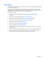
Front Bezel The front bezel is located on the front of the computer and is secured to the main system bracket with five Torx screws and nine tabs. You can remove the front bezel without disassembling many of the computer's components. Most components can remain attached to the base pan. The following procedure demonstrates removing the bezel while removing the smallest number of components possible. To remove the front bezel: 1. Prepare the computer for disassembly (see Preparing to Disassemble the Computer on page 26). 2. Remove the center access panel (see Hinge Cover Panel on page 27). 3. Remove the memory access panel (see Memory Access Panel on page 29). 4. Remove the drive access panel (see Drive Access Panel on page 31). 5. Remove the top panel (see Top Panel on page 51). 6. Remove the rear cover (see Rear Cover on page 55). 7. Remove the speakers (see Speakers on page 66). 8. Remove the power switch assembly cable from the front bezel. You do not have to remove the remaining cables. 9. Remove the five black Torx screws that secure the bezel to the main system bracket assembly. 10. Lift the nine tabs (see arrows in image) that secure the bezel to the main system bracket assembly. Be sure to slide the bracket free from the tabs as you lift each one. Front Bezel 77
-
 1
1 -
2
-
3
-
4
-
5
-
6
-
7
-
8
-
9
-
10
-
11
-
12
-
13
-
14
-
15
-
16
-
17
-
18
-
19
-
20
-
21
-
22
-
23
-
24
-
25
-
26
-
27
-
28
-
29
-
30
-
31
-
32
-
33
-
34
-
35
-
36
-
37
-
38
-
39
-
40
-
41
-
42
-
43
-
44
-
45
-
46
-
47
-
48
-
49
-
50
-
51
-
52
-
53
-
54
-
55
-
56
-
57
-
58
-
59
-
60
-
61
-
62
-
63
-
64
-
65
-
66
-
67
-
68
-
69
-
70
-
71
-
72
-
73
-
74
-
75
-
76
-
77
-
78
-
79
-
 80
80 -
 81
81 -
 82
82 -
 83
83 -
 84
84 -
 85
85 -
 86
86 -
 87
87 -
 88
88 -
 89
89 -
 90
90 -
91
-
92
-
93
-
94
-
95
-
96
-
97
-
98
-
99
-
100
-
101
-
102
-
103
-
104
-
105
-
106
-
107
-
108
-
109
-
110
-
111
-
112
-
113
-
114
-
115
-
116
-
117
-
118
-
119
-
120
-
121
-
122
-
123
-
124
-
125
-
126
-
127
-
128
-
129
-
130
-
131
-
132
-
133
 |
 |
