HP Surestore Tape Library Model 6/140 HP SureStore E Tape Library Model 6/140 - Page 162
Removing a Drive Module, Ribbon Cable and Connector
 |
View all HP Surestore Tape Library Model 6/140 manuals
Add to My Manuals
Save this manual to your list of manuals |
Page 162 highlights
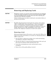
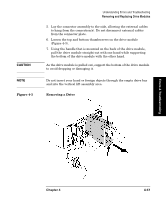
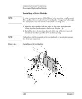
NOTE CAUTION Figure 4-2 Understanding Errors and Troubleshooting Removing and Replacing Drive Modules Removing a Drive Module To preserve SCSI communications, do not loosen or remove the SCSI cable(s) connected to the outside of the drive module. The connection to be removed is located inside the drive module. When the drive module has been successfully taken offline, one of the LEDs on the back of the drive will be flashing yellow. Remove the drive module using the steps below: 1. Verify the external SCSI cable is tightened to the connector plate. 2. Loosen the thumbscrews on each side of the connector plate, located in the middle of the drive module (Figure 4-2). If this is your first time loosening the thumbscrews, use a screwdriver. 3. Gently remove the connector plate, with SCSI cable(s) still connected. Use standard precautions for electro-static discharge (ESD) protection. 4. Grasp the ribbon cable that is plugged into the drive module. Remove the cable by pulling the connector to the left. See Figure 4-2 for the location of the ribbon cable and connector. Ribbon Cable and Connector 4-56 Chapter 4
-
 1
1 -
2
-
3
-
4
-
5
-
6
-
7
-
8
-
9
-
10
-
11
-
12
-
13
-
14
-
15
-
16
-
17
-
18
-
19
-
20
-
21
-
22
-
23
-
24
-
25
-
26
-
27
-
28
-
29
-
30
-
31
-
32
-
33
-
34
-
35
-
36
-
37
-
38
-
39
-
40
-
41
-
42
-
43
-
44
-
45
-
46
-
47
-
48
-
49
-
50
-
51
-
52
-
53
-
54
-
55
-
56
-
57
-
58
-
59
-
60
-
61
-
62
-
63
-
64
-
65
-
66
-
67
-
68
-
69
-
70
-
71
-
72
-
73
-
74
-
75
-
76
-
77
-
78
-
79
-
80
-
81
-
82
-
83
-
84
-
85
-
86
-
87
-
88
-
89
-
90
-
91
-
92
-
93
-
94
-
95
-
96
-
97
-
98
-
99
-
100
-
101
-
102
-
103
-
104
-
105
-
106
-
107
-
108
-
109
-
110
-
111
-
112
-
113
-
114
-
115
-
116
-
117
-
118
-
119
-
120
-
121
-
122
-
123
-
124
-
125
-
126
-
127
-
128
-
129
-
130
-
131
-
132
-
133
-
134
-
135
-
136
-
137
-
138
-
139
-
140
-
141
-
142
-
143
-
144
-
145
-
146
-
147
-
148
-
149
-
150
-
151
-
152
-
153
-
154
-
155
-
156
-
 157
157 -
 158
158 -
 159
159 -
 160
160 -
 161
161 -
 162
162 -
 163
163 -
 164
164 -
 165
165 -
 166
166 -
 167
167 -
168
-
169
-
170
-
171
-
172
-
173
-
174
-
175
-
176
-
177
-
178
-
179
-
180
-
181
-
182
-
183
-
184
-
185
-
186
-
187
-
188
-
189
-
190
-
191
-
192
-
193
-
194
-
195
-
196
-
197
-
198
-
199
-
200
-
201
-
202
-
203
-
204
-
205
-
206
-
207
-
208
-
209
-
210
-
211
-
212
-
213
-
214
-
215
-
216
-
217
-
218
-
219
-
220
-
221
-
222
-
223
-
224
-
225
-
226
-
227
-
228
-
229
-
230
-
231
-
232
-
233
-
234
-
235
-
236
-
237
-
238
-
239
-
240
 |
 |
