HP Surestore Tape Library Model 6/140 HP SureStore E Tape Library Model 6/140 - Page 33
Connect a SCSI jumper cable from the top connector on the library
 |
View all HP Surestore Tape Library Model 6/140 manuals
Add to My Manuals
Save this manual to your list of manuals |
Page 33 highlights
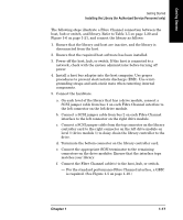
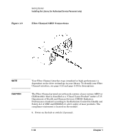
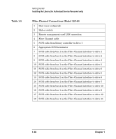
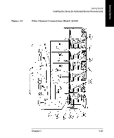
Getting Started Getting Started Installing the Library (for Authorized Service Personnel only) The following steps illustrate a Fibre Channel connection between the host, hub or switch, and library. Refer to Table 1-5 on page 1-20 and Figure 1-6 on page 1-21, and connect the library as follows: 1. Ensure that the library and host are inactive, and the library is disconnected from the host. 2. Ensure that the required host software has been installed. 3. Power off the host, hub, or switch. If the host is connected to a network, check with the system administrator before turning off power. 4. Install a host bus adapter into the host computer. Use proper procedures to prevent electrostatic discharge (ESD). Use wristgrounding straps and anti-static mats when removing internal components. 5. Connect the hardware. a. On each level of the library that has a drive module, connect a SCSI jumper cable from bus 1 on each Fibre Channel interface to the left connector on the left drive module. b. Connect a SCSI jumper cable from bus 2 on each Fibre Channel interface to the left connector on the right drive module. c. Connect a SCSI jumper cable from the top connector on the library controller card to the right connector on the left drive module on level 1 (drive module 1) to daisy-chain the library controller to the drive. d. Terminate the bottom connector on the library controller card. e. Connect the appropriate SCSI terminator to the remaining connectors on the drive modules. Ensure that the interface type matches your library. f. Connect the Fibre Channel cable(s) to the host, hub, or switch. - For the standard performance Fibre Channel interface, a GBIC is required. (See Figure 1-5 on page 1-18.) Chapter 1 1-17
-
 1
1 -
2
-
3
-
4
-
5
-
6
-
7
-
8
-
9
-
10
-
11
-
12
-
13
-
14
-
15
-
16
-
17
-
18
-
19
-
20
-
21
-
22
-
23
-
24
-
25
-
26
-
27
-
 28
28 -
 29
29 -
 30
30 -
 31
31 -
 32
32 -
 33
33 -
 34
34 -
 35
35 -
 36
36 -
 37
37 -
 38
38 -
39
-
40
-
41
-
42
-
43
-
44
-
45
-
46
-
47
-
48
-
49
-
50
-
51
-
52
-
53
-
54
-
55
-
56
-
57
-
58
-
59
-
60
-
61
-
62
-
63
-
64
-
65
-
66
-
67
-
68
-
69
-
70
-
71
-
72
-
73
-
74
-
75
-
76
-
77
-
78
-
79
-
80
-
81
-
82
-
83
-
84
-
85
-
86
-
87
-
88
-
89
-
90
-
91
-
92
-
93
-
94
-
95
-
96
-
97
-
98
-
99
-
100
-
101
-
102
-
103
-
104
-
105
-
106
-
107
-
108
-
109
-
110
-
111
-
112
-
113
-
114
-
115
-
116
-
117
-
118
-
119
-
120
-
121
-
122
-
123
-
124
-
125
-
126
-
127
-
128
-
129
-
130
-
131
-
132
-
133
-
134
-
135
-
136
-
137
-
138
-
139
-
140
-
141
-
142
-
143
-
144
-
145
-
146
-
147
-
148
-
149
-
150
-
151
-
152
-
153
-
154
-
155
-
156
-
157
-
158
-
159
-
160
-
161
-
162
-
163
-
164
-
165
-
166
-
167
-
168
-
169
-
170
-
171
-
172
-
173
-
174
-
175
-
176
-
177
-
178
-
179
-
180
-
181
-
182
-
183
-
184
-
185
-
186
-
187
-
188
-
189
-
190
-
191
-
192
-
193
-
194
-
195
-
196
-
197
-
198
-
199
-
200
-
201
-
202
-
203
-
204
-
205
-
206
-
207
-
208
-
209
-
210
-
211
-
212
-
213
-
214
-
215
-
216
-
217
-
218
-
219
-
220
-
221
-
222
-
223
-
224
-
225
-
226
-
227
-
228
-
229
-
230
-
231
-
232
-
233
-
234
-
235
-
236
-
237
-
238
-
239
-
240
 |
 |
