IBM 8872 Service Guide - Page 135
Power-supply, structure
 |
UPC - 000435813060
View all IBM 8872 manuals
Add to My Manuals
Save this manual to your list of manuals |
Page 135 highlights
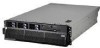
9. If you are instructed to return the PCI-X adapter guide, follow all packaging instructions, and use any packaging materials for shipping that are supplied to you. To install the replacement PCI-X adapter guide, complete the following steps: 1. Align the two tabs on the PCI-X adapter guide with the two slots on the chassis. 2. Set the guide firmly into place and turn the quarter-turn fasteners to secure the guide. 3. Reconnect the cables that pass through the PCI-X adapter guide and route the cables through the routing feature of the guide. 4. Install the adapters and dividers. 5. When replacing the dividers, make sure that the tabs on the bottom of the dividers rest in the holes in the bottom of the metal section of the guide and the tabs on the top of the dividers engage the plastic retainer section of the guide. 6. Lower the latch mechanism. 7. Install the top cover (see "Top cover and bezel" on page 113). 8. Slide the server into the rack. 9. Connect the cables and power cords (see "Completing the installation" in the Installation Guide or User's Guide for cabling instructions). 10. Turn on all attached devices and the server. Power-supply structure To remove the power-supply structure, complete the following steps: Latches Alignment tabs Handle Alignment pins 1. Read the safety information that begins on page vii and "Installation guidelines" on page 99. 2. Turn off the server and peripheral devices, and disconnect the power cords and all external cables necessary to replace the device. 3. Remove the top cover (see "Top cover and bezel" on page 113). 4. Remove the memory cards (see "Removing and replacing a memory card" on page 108). Chapter 4. Removing and replacing server components 119
-
 1
1 -
2
-
3
-
4
-
5
-
6
-
7
-
8
-
9
-
10
-
11
-
12
-
13
-
14
-
15
-
16
-
17
-
18
-
19
-
20
-
21
-
22
-
23
-
24
-
25
-
26
-
27
-
28
-
29
-
30
-
31
-
32
-
33
-
34
-
35
-
36
-
37
-
38
-
39
-
40
-
41
-
42
-
43
-
44
-
45
-
46
-
47
-
48
-
49
-
50
-
51
-
52
-
53
-
54
-
55
-
56
-
57
-
58
-
59
-
60
-
61
-
62
-
63
-
64
-
65
-
66
-
67
-
68
-
69
-
70
-
71
-
72
-
73
-
74
-
75
-
76
-
77
-
78
-
79
-
80
-
81
-
82
-
83
-
84
-
85
-
86
-
87
-
88
-
89
-
90
-
91
-
92
-
93
-
94
-
95
-
96
-
97
-
98
-
99
-
100
-
101
-
102
-
103
-
104
-
105
-
106
-
107
-
108
-
109
-
110
-
111
-
112
-
113
-
114
-
115
-
116
-
117
-
118
-
119
-
120
-
121
-
122
-
123
-
124
-
125
-
126
-
127
-
128
-
129
-
 130
130 -
 131
131 -
 132
132 -
 133
133 -
 134
134 -
 135
135 -
 136
136 -
 137
137 -
 138
138 -
 139
139 -
 140
140 -
141
-
142
-
143
-
144
-
145
-
146
-
147
-
148
-
149
-
150
-
151
-
152
-
153
-
154
-
155
-
156
-
157
-
158
-
159
-
160
-
161
-
162
-
163
-
164
-
165
-
166
-
167
-
168
-
169
-
170
 |
 |
