IBM 8872 Service Guide - Page 21
Release, latch, System-error, Locator, drive, activity, Power-on, Electrostatic-discharge, connector
 |
UPC - 000435813060
View all IBM 8872 manuals
Add to My Manuals
Save this manual to your list of manuals |
Page 21 highlights
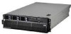
Rear view v Release latch: Slide this latch to the left to access the light path diagnostics panel. v System-error LED: When this LED is lit, it indicates that a system error has occurred. An LED on the light path diagnostics panel is also lit to help isolate the error. v Locator LED: When this LED is lit, it has been lit remotely by the system administrator to aid in visually locating the server. In multi-node configurations, when this LED flashes during startup, it indicates that the server is the primary node. When this LED is lit during startup, it indicates that the server is a secondary node. v Hard disk drive activity LED: When this LED is flashing, it indicates that a SAS hard disk drive is in use. v Power-on LED: When this LED is lit and not flashing, it indicates that the server is turned on. When this LED is flashing, it indicates that the server is turned off and still connected to an ac power source. When this LED is off, it indicates that ac power is not present, or the power supply or the LED itself has failed. Note: If this LED is off, it does not mean that there is no electrical power in the server. The LED might be burned out. To remove all electrical power from the server, you must disconnect the power cords from the electrical outlets. Electrostatic-discharge connector: Connect an electrostatic-discharge wrist strap to this connector. DVD drive activity LED: (Standard on some models only) When this LED is lit, it indicates that the DVD drive is in use. DVD-eject button: (Standard on some models only) Press this button to release a CD or DVD from the DVD drive. The following illustration shows the connectors and LEDs on the rear of the server. SMP expansion port 3 link LED SMP expansion port 3 SMP expansion port 2 link LED SMP expansion port 2 SMP expansion port 1 SMP expansion port 1 link LED SP Ethernet 10/100 USB 1 Video SP Ethernet 10/100 activity LED SP Ethernet 10/100 link LED USB 2 System serial SP serial Power-supply Gigabit Ethernet 1 link LED Gigabit Ethernet 1 Gigabit Ethernet 1 activity LED Gigabit Ethernet 2 link LED Gigabit Ethernet 2 Mouse Keyboard Remote Supervisor Adapter II SlimLine error LED IXA RS485 I/O board error LED Gigabit Ethernet 2 activity LED Chapter 1. Introduction 5
-
 1
1 -
2
-
3
-
4
-
5
-
6
-
7
-
8
-
9
-
10
-
11
-
12
-
13
-
14
-
15
-
 16
16 -
 17
17 -
 18
18 -
 19
19 -
 20
20 -
 21
21 -
 22
22 -
 23
23 -
 24
24 -
 25
25 -
 26
26 -
27
-
28
-
29
-
30
-
31
-
32
-
33
-
34
-
35
-
36
-
37
-
38
-
39
-
40
-
41
-
42
-
43
-
44
-
45
-
46
-
47
-
48
-
49
-
50
-
51
-
52
-
53
-
54
-
55
-
56
-
57
-
58
-
59
-
60
-
61
-
62
-
63
-
64
-
65
-
66
-
67
-
68
-
69
-
70
-
71
-
72
-
73
-
74
-
75
-
76
-
77
-
78
-
79
-
80
-
81
-
82
-
83
-
84
-
85
-
86
-
87
-
88
-
89
-
90
-
91
-
92
-
93
-
94
-
95
-
96
-
97
-
98
-
99
-
100
-
101
-
102
-
103
-
104
-
105
-
106
-
107
-
108
-
109
-
110
-
111
-
112
-
113
-
114
-
115
-
116
-
117
-
118
-
119
-
120
-
121
-
122
-
123
-
124
-
125
-
126
-
127
-
128
-
129
-
130
-
131
-
132
-
133
-
134
-
135
-
136
-
137
-
138
-
139
-
140
-
141
-
142
-
143
-
144
-
145
-
146
-
147
-
148
-
149
-
150
-
151
-
152
-
153
-
154
-
155
-
156
-
157
-
158
-
159
-
160
-
161
-
162
-
163
-
164
-
165
-
166
-
167
-
168
-
169
-
170
 |
 |
