IBM 8872 Service Guide - Page 136
backplane
 |
UPC - 000435813060
View all IBM 8872 manuals
Add to My Manuals
Save this manual to your list of manuals |
Page 136 highlights
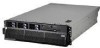
5. Remove the power supplies (see "Hot-swap power supply" on page 106). 6. Pull the two blue latches on the power-supply structure toward the front of the server; the structure will disengage from the chassis. 7. Grasp the handle in the middle of the structure and rotate the structure up, allowing the structure to pivot at the chassis front. 8. Lift the structure out of the server, and make sure that the alignment tabs clear the chassis. 9. If you are instructed to return the power-supply structure, follow all packaging instructions, and use any packaging materials for shipping that are supplied to you. To install the replacement power-supply structure, complete the following steps. Attention: Do not allow any cables to be pinched or caught on metal protrusions. 1. Align the tabs on the power-supply structure with the notches on the rear of the chassis; then, gently lower the structure into the server. Make sure that the structure is firmly seated in the chassis. 2. Push the two blue latches of the power-supply structure toward the rear of the server until they lock the structure into position. 3. Replace the power supplies. 4. Replace the memory cards. 5. Install the top cover (see "Top cover and bezel" on page 113). 6. Slide the server into the rack. 7. Connect the cables and power cords (see "Completing the installation" in the Installation Guide or User's Guide for cabling instructions). 8. Turn on all attached devices and the server. SAS backplane To remove the Serial Attached SCSI (SAS) backplane, complete the following steps: Release tabs SAS connectors Guide channels 120 IBM xSeries 460 Type 8872 and xSeries MXE 460 Type 8874: Problem Determination and Service Guide
-
 1
1 -
2
-
3
-
4
-
5
-
6
-
7
-
8
-
9
-
10
-
11
-
12
-
13
-
14
-
15
-
16
-
17
-
18
-
19
-
20
-
21
-
22
-
23
-
24
-
25
-
26
-
27
-
28
-
29
-
30
-
31
-
32
-
33
-
34
-
35
-
36
-
37
-
38
-
39
-
40
-
41
-
42
-
43
-
44
-
45
-
46
-
47
-
48
-
49
-
50
-
51
-
52
-
53
-
54
-
55
-
56
-
57
-
58
-
59
-
60
-
61
-
62
-
63
-
64
-
65
-
66
-
67
-
68
-
69
-
70
-
71
-
72
-
73
-
74
-
75
-
76
-
77
-
78
-
79
-
80
-
81
-
82
-
83
-
84
-
85
-
86
-
87
-
88
-
89
-
90
-
91
-
92
-
93
-
94
-
95
-
96
-
97
-
98
-
99
-
100
-
101
-
102
-
103
-
104
-
105
-
106
-
107
-
108
-
109
-
110
-
111
-
112
-
113
-
114
-
115
-
116
-
117
-
118
-
119
-
120
-
121
-
122
-
123
-
124
-
125
-
126
-
127
-
128
-
129
-
130
-
 131
131 -
 132
132 -
 133
133 -
 134
134 -
 135
135 -
 136
136 -
 137
137 -
 138
138 -
 139
139 -
 140
140 -
 141
141 -
142
-
143
-
144
-
145
-
146
-
147
-
148
-
149
-
150
-
151
-
152
-
153
-
154
-
155
-
156
-
157
-
158
-
159
-
160
-
161
-
162
-
163
-
164
-
165
-
166
-
167
-
168
-
169
-
170
 |
 |
