Icom IC-R8600 Instruction Manual - Page 13
Touch panel display, BLANK MEMORY CHANNEL INDICATOR p. 8-3
 |
View all Icom IC-R8600 manuals
Add to My Manuals
Save this manual to your list of manuals |
Page 13 highlights
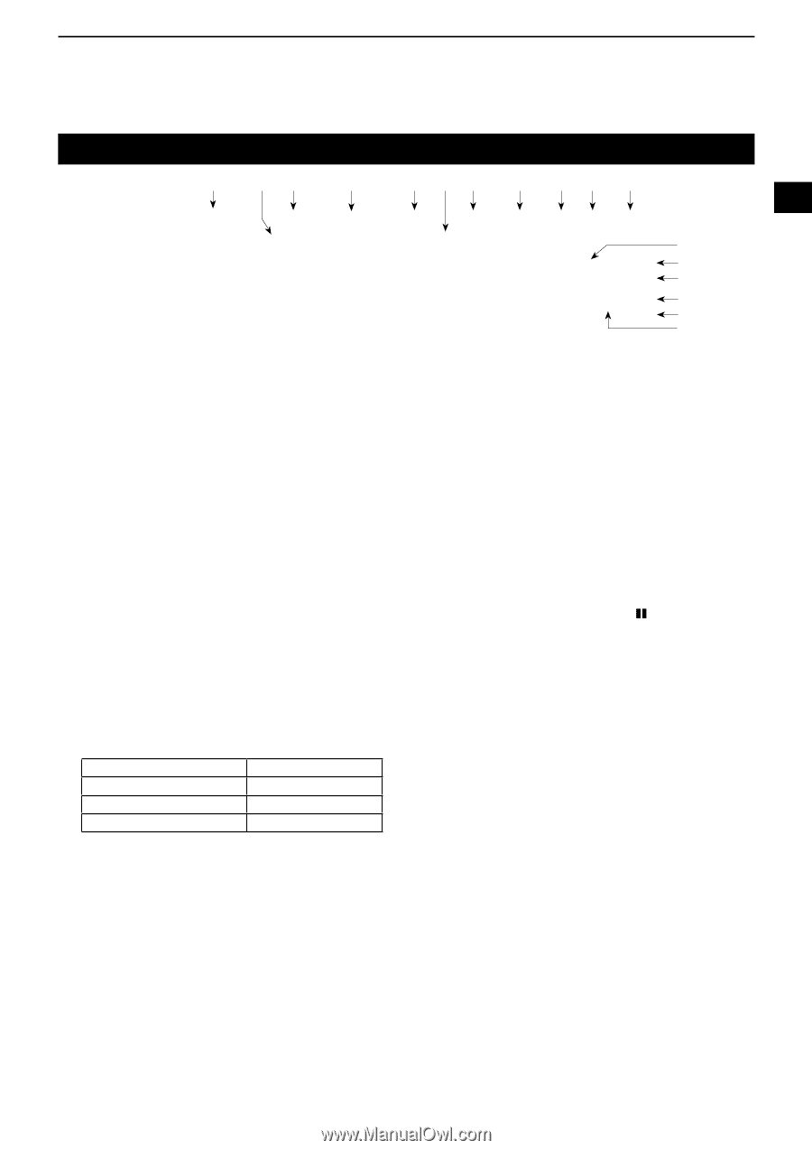
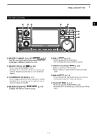
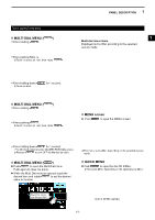
1 PANEL DESCRIPTION Touch panel display q we r t y u i o !0 !1 1 2 !2 !3 3 !4 !5 4 !6 !7 5 6 7 8 9 (This screen is only an example.) 10 q MODE INDICATOR (p. 3-1) Displays the selected receive mode. o NETWORK CONTROL INDICATOR Is displayed while the IC-R8600 is remotely 11 w VSC INDICATOR (pp. 9-11, 5-10) controlled by the optional RS-R8600, through the network. 12 Appears while the Voice Squelch Control (VSC) function is ON. !0 VOICE RECORDER ICON / (p. 6-1) 13 SCRM: Appears while the Scrambler function is ON. Is displayed while recording to indicate the ENCR: Appears while the Encryption function is ON. recording status. 14 e PASSBAND WIDTH INDICATOR (BW/SFT) (pp. 5-2, 5-9) • Graphically displays the digital IF filter passband width and the shift amount. • While the Tone/Digital Squelch function is ON, displays the tone/digital squelch type. TSQL: Tone squelch COM ID: Common ID DTCS: Digital tone squelch CC: - CSQL: Digital code squelch RAN: Radio access number NAC: Network access code UC: User code r IF FILTER INDICATOR (p. 5-3) Displays the selected IF filter (FIL1, FIL2 or FIL3). t PREAMP INDICATOR (pp. 1-7, 5-1) Is displayed while the preamplifier is ON. y MEMORY NAME READOUT (p. 8-5) Displays the memory name if entered. u ATTENUATOR INDICATOR (ATT10/ATT20/ATT30) (pp. 1-7, 5-1) Is displayed while the attenuator is ON. i IP+ ICON (pp. 1-7, 5-2) Is displayed while the IP Plus function is ON. !1 CLOCK READOUT (p. 10-1) Displays the current local time. 15 LTouch the readout to display both the current local time and UTC time. 16 !2 AFC INDICATOR (p. 5-5) 17 Is displayed while the Automatic Frequency Control (AFC) function is ON. 18 !3 SKIP INDICATOR (pp. 9-9, 9-10) SKIP: Memory Skip 19 PSKIP: Program Skip 20 !4 OPERATING MODE INDICATOR (p. 3-1) VFO: VFO mode 21 MEMO: Memory mode !5 MEMORY CHANNEL READOUT (pp. 3-1, 8-2) Displays the selected memory channel number. !6 BLANK MEMORY CHANNEL INDICATOR (p. 8-3) Is displayed when the selected memory channel is blank. !7 MEMORY CHANNEL GROUP INDICATOR (p. 8-1) 00~99: Memory channel group number A: Auto memory write group S: Scan skip group P: Programmable scan edge group 1-4
-
 1
1 -
2
-
3
-
4
-
5
-
6
-
7
-
 8
8 -
 9
9 -
 10
10 -
 11
11 -
 12
12 -
 13
13 -
 14
14 -
 15
15 -
 16
16 -
 17
17 -
 18
18 -
19
-
20
-
21
-
22
-
23
-
24
-
25
-
26
-
27
-
28
-
29
-
30
-
31
-
32
-
33
-
34
-
35
-
36
-
37
-
38
-
39
-
40
-
41
-
42
-
43
-
44
-
45
-
46
-
47
-
48
-
49
-
50
-
51
-
52
-
53
-
54
-
55
-
56
-
57
-
58
-
59
-
60
-
61
-
62
-
63
-
64
-
65
-
66
-
67
-
68
-
69
-
70
-
71
-
72
-
73
-
74
-
75
-
76
-
77
-
78
-
79
-
80
-
81
-
82
-
83
-
84
-
85
-
86
-
87
-
88
-
89
-
90
-
91
-
92
-
93
-
94
-
95
-
96
 |
 |