Icom IC-R8600 Instruction Manual - Page 14
Noise Blanker Indicator Nb Pp. 1-7
 |
View all Icom IC-R8600 manuals
Add to My Manuals
Save this manual to your list of manuals |
Page 14 highlights
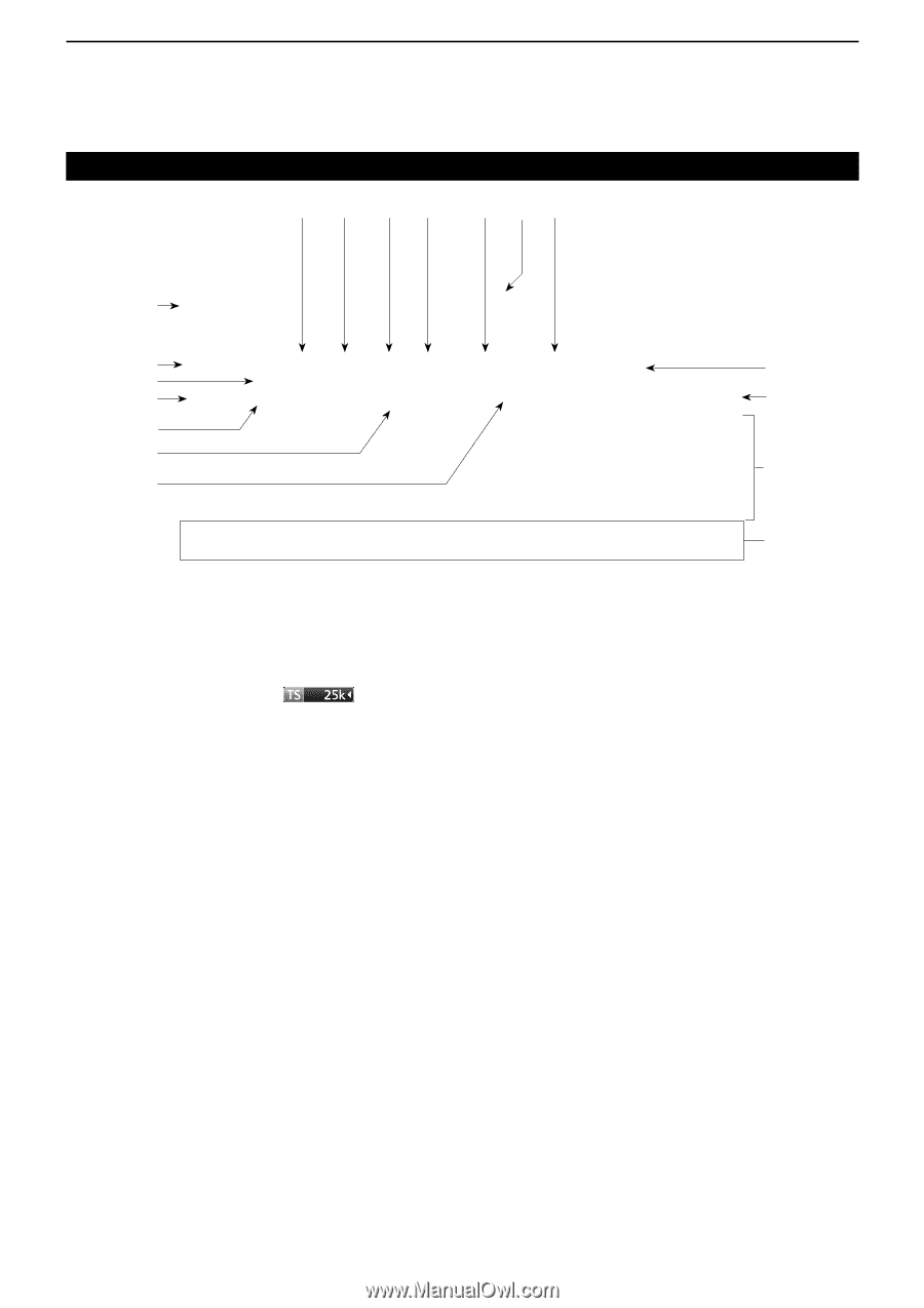
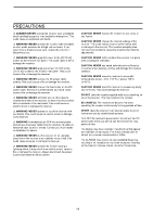
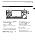
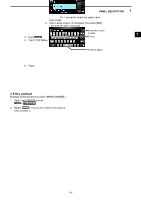
1 PANEL DESCRIPTION Touch panel (Continued) @9 #0 #1 #2 #3 #4 #5 @8 @7 !8 @6 @5 !9 @4 @3 @0 @2 @1 (This screen is only an example.) !8 PRIORITY INDICATOR (p. 9-2) Is displayed during a Priority scan. LBlinks while the squelch is forced to open during a Priority scan. (p. 9-3) @6 OVERFLOW (OVF) INDICATOR (pp. 3-1, 5-1) Is displayed when an excessively strong signal is received. (Normally, "S" is displayed to in the S-Meter mode) !9 TUNING STEP INDICATOR (p. 3-2) Displays the currently selected tuning step. LIf the tuning step is set by the programmable tuning step, "◄" is displayed by the indicator. @0 FUNCTION SCREEN Displays the operating parameters, modes, frequencies and indicators, depending on your selections. @1 FUNCTION GUIDES Displays the currently accessible function. @2 RECEIVED SIGNAL STRENGTH INDICATOR (p. 3-4) Displays the absolute received signal strength in terminated or open load measurement. @3 SIGNAL METER (p. 3-4) Indicates the signal strength in S-meter/dBµ/ dBµ(EMF)/dBm. @4 RF GAIN (RFG) (p. 3-1) Is displayed when the RF gain is set to less than 100% to indicate that the RF gain is reduced. @5 TUNING INDICATOR (p. 3-4) Displays the detuned level in the FM, WFM, FSK and DIGITAL modes. @7 AGC INDICATOR (pp. 1-7, 5-1) Displays the selected AGC time constant setting. (AGC-F: Fast, AGC-M: Mid, AGC-S: Slow or AGC-OFF: OFF). @8 ANTENNA INDICATOR (p. 3-3, 5-1) Displays the selected antenna (ANT1, ANT2 or ANT3) only when the frequency is set to 10 kHz ~ 29.999999 MHz. @9 NOTCH INDICATOR (AN/MN) (pp. 1-7, 5-2) Is displayed while the Notch function is ON. (AN: Auto Notch or MN: Manual Notch) #0 NOISE BLANKER INDICATOR (NB) (pp. 1-7, 5-4) Is displayed while the Noise Blanker function is ON. #1 NOISE REDUCTION INDICATOR (NR) (p. 1-7, 5-4) Is displayed while the Noise Reduction function is ON. #2 TWIN PEAK FILTER INDICATOR (TPF) (p. 5-7) Is displayed while the Twin Peak Filter function is ON. #3 DUP INDICATOR (DUP-/DUP+) (pp. 1-7, 5-4) Is displayed while in the Duplex mode. #4 TS INDICATOR ("▼") (p. 3-2) Is displayed when the TS function is on. The frequency changes according to the tuning step set in TUNING STEP INDICATOR (!9). LTouch kHz digit to turn OFF the TS function. #5 MONITOR INDICATOR (MONI) (p. 3-1) Appears while the Monitor function is ON. 1-5
-
 1
1 -
2
-
3
-
4
-
5
-
6
-
7
-
8
-
 9
9 -
 10
10 -
 11
11 -
 12
12 -
 13
13 -
 14
14 -
 15
15 -
 16
16 -
 17
17 -
 18
18 -
 19
19 -
20
-
21
-
22
-
23
-
24
-
25
-
26
-
27
-
28
-
29
-
30
-
31
-
32
-
33
-
34
-
35
-
36
-
37
-
38
-
39
-
40
-
41
-
42
-
43
-
44
-
45
-
46
-
47
-
48
-
49
-
50
-
51
-
52
-
53
-
54
-
55
-
56
-
57
-
58
-
59
-
60
-
61
-
62
-
63
-
64
-
65
-
66
-
67
-
68
-
69
-
70
-
71
-
72
-
73
-
74
-
75
-
76
-
77
-
78
-
79
-
80
-
81
-
82
-
83
-
84
-
85
-
86
-
87
-
88
-
89
-
90
-
91
-
92
-
93
-
94
-
95
-
96
 |
 |