Icom IC-V8000 Instruction Manual - Page 13
Tone/tone Scan Switch [tonet-scan] - mic
 |
View all Icom IC-V8000 manuals
Add to My Manuals
Save this manual to your list of manuals |
Page 13 highlights
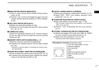
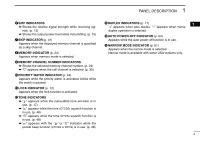
PANEL DESCRIPTION 1 y BANK•OPTION SWITCH [BANK(OPT)] ➥ Push to select memory bank condition during memory mode. (p. 32) ➥ Push for 1 sec. to select and toggle the pager and code squelch function when the optional UT-108 is installed. (p. 52) u SET•LOCK SWITCH [SET(LOCK)] ➥ Enters set mode when pushed. (p. 58) ➥ Switches the lock function ON and OFF when pushed for 1 sec. (p. 12) i TUNING DIAL [DIAL] Selects the operating frequency (p. 9), memory channel (p. 24), the setting of the set mode item and the scanning direction (p. 38). o MEMORY WRITE SWITCH [MW(S.MW)] (p. 25) ➥ Selects a memory channel for programming. ➥ Programs the selected memory channel when pushed for 1 sec. • Continue to hold the switch to increment the memory channel automatically. !0 MONITOR•CHANNEL NAME SWITCH [MONI(ANM)] ➥ Push to switch the monitor function ON and OFF. (p. 13) ➥ In memory and call channel mode, switches the channel names or number ON and OFF. (p. 30) !1 OUTPUT POWER SWITCH [LOW(DUP)] 1 ➥ Each push changes the output power selection. (p. 15) ➥ Select DUP-, DUP+ and simplex operation when pushed for 1 sec. (p. 17) !2 TONE/TONE SCAN SWITCH [TONE(T-SCAN)] ➥ Each push selects a tone function. (pgs. 17, 48) • Tone encoder, pocket beep, tone squelch or tone function OFF can be selected. ➥ Push for 1 sec. to start/stop the tone scan function. (p. 51) !3 VFO/MHz TUNING•SCAN SWITCH [V/MHz(SCAN)] ➥ Selects and toggles VFO mode and 1 MHz (or 10 MHz for some versions) tuning when pushed. (p. 9) ➥ Starts scan when pushed for 1 sec. (p. 38) • Cancels a scan when pushed during scan. D Microphone connector (front panel view) q +8 V DC output (Max. 10 mA) w Channel up/down e 8 V control IN q i r PTT t GND (microphone ground) y MIC (microphone input) u GND i Data IN 2
-
 1
1 -
2
-
3
-
4
-
5
-
6
-
7
-
 8
8 -
 9
9 -
 10
10 -
 11
11 -
 12
12 -
 13
13 -
 14
14 -
 15
15 -
 16
16 -
 17
17 -
 18
18 -
19
-
20
-
21
-
22
-
23
-
24
-
25
-
26
-
27
-
28
-
29
-
30
-
31
-
32
-
33
-
34
-
35
-
36
-
37
-
38
-
39
-
40
-
41
-
42
-
43
-
44
-
45
-
46
-
47
-
48
-
49
-
50
-
51
-
52
-
53
-
54
-
55
-
56
-
57
-
58
-
59
-
60
-
61
-
62
-
63
-
64
-
65
-
66
-
67
-
68
-
69
-
70
-
71
-
72
-
73
-
74
-
75
-
76
-
77
-
78
-
79
-
80
-
81
-
82
-
83
-
84
-
85
-
86
-
87
-
88
 |
 |
