Icom IC-V8000 Instruction Manual - Page 17
Microphone
 |
View all Icom IC-V8000 manuals
Add to My Manuals
Save this manual to your list of manuals |
Page 17 highlights
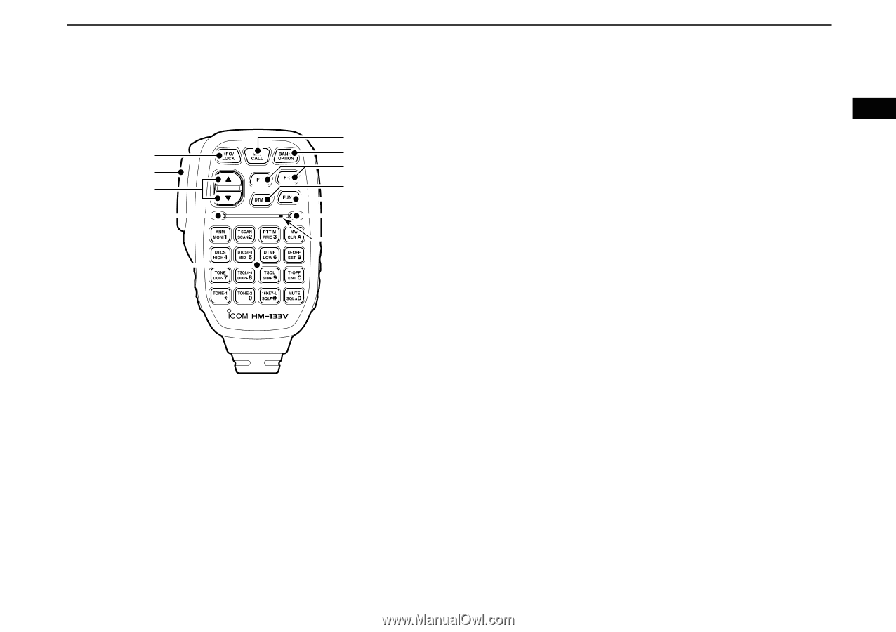
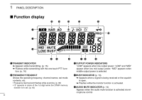
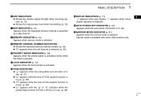
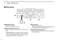
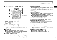
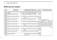
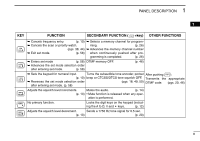
PANEL DESCRIPTION 1 Microphone (HM-133V*) !1 q !0 w o e i u r y Mic element t *A different microphone may be supplied depending on version. q VFO/LOCK SWITCH [VFO/LOCK] ➥ Push to select VFO mode. (p. 9) ➥ Push for 1 sec. to switch the lock function ON and OFF. (p. 12) w PTT SWITCH ➥ Push and hold to transmit; release to receive. ➥ Switches between transmitting and receiving while the one-touch PTT function is in use. (p. 16) e UP/DOWN SWITCHES [Y]/[Z] ➥ Push either switch to change operating frequency, memory channel, set mode setting, etc. (pgs. 10, 24) ➥ Push either switch for 1 sec. to start scanning. (p. 38) r ACTIVITY INDICATOR 1 ➥ Lights red while any key, except [FUNC] and [DTMF-S], is pushed, or while transmitting. ➥ Lights green while the one-touch PTT function is in use. t KEYPAD (pgs. 7, 8) y FUNCTION INDICATOR ➥ Lights orange while [FUNC] is activated-indicates the secondary function of switches can be accessed. ➥ Lights green when [DTMF-S] is activated-DTMF signals can be transmitted with the keypad. u FUNCTION SWITCH [FUNC] (pgs. 7, 8) i DTMF MEMORY SELECT SWITCH [DTMF-S] (p. 46) o FUNCTION SWITCHES [F-1]/[F-2] (p. 67) Program and re-call your desired transceiver conditions. !0 BANK/OPTION SWITCH [BANK/OPTION] ➥ Push to selects memory bank condition during memory mode. (p. 32) ➥ Push for 1 sec. to select and toggle pager and code squelch function when the optional UT-108 is installed. (p. 52) !1 MEMORY/CALL SWITCH [MR/CALL] ➥ Push to select memory mode. (p. 24) ➥ Push for 1 sec. to select call channel. (p. 35) 6
-
 1
1 -
2
-
3
-
4
-
5
-
6
-
7
-
8
-
9
-
10
-
11
-
 12
12 -
 13
13 -
 14
14 -
 15
15 -
 16
16 -
 17
17 -
 18
18 -
 19
19 -
 20
20 -
 21
21 -
 22
22 -
23
-
24
-
25
-
26
-
27
-
28
-
29
-
30
-
31
-
32
-
33
-
34
-
35
-
36
-
37
-
38
-
39
-
40
-
41
-
42
-
43
-
44
-
45
-
46
-
47
-
48
-
49
-
50
-
51
-
52
-
53
-
54
-
55
-
56
-
57
-
58
-
59
-
60
-
61
-
62
-
63
-
64
-
65
-
66
-
67
-
68
-
69
-
70
-
71
-
72
-
73
-
74
-
75
-
76
-
77
-
78
-
79
-
80
-
81
-
82
-
83
-
84
-
85
-
86
-
87
-
88
 |
 |