Intel SPSH4 Product Guide - Page 135
Peripheral Device Bay, Hot-Swap Hard Drive Bays
 |
UPC - 735858156462
View all Intel SPSH4 manuals
Add to My Manuals
Save this manual to your list of manuals |
Page 135 highlights
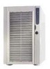
Peripheral Device Bay Opening the right bezel door provides access to the peripheral bay. The peripheral bay consists of four bays for removable media: • A 3.5-inch bay comes with a 3.5-inch diskette drive installed. • Three half-height bays accommodate 5.25-inch drives. One bay comes with a CD-ROM drive installed. CAUTION Intel does not recommend installing a hard disk drive in the 5.25-inch bay, because of potential cooling and electromagnetic interference (EMI) constraints. Hot-Swap Hard Drive Bays The server comes with one hot-swap hard drive bay installed. A second bay is available as an accessory. The hard drive bays each support up to five 3.5-inch by 1.0-inch Ultra160 SCSI hard drives. The hard drive bays also support SCSI hard drive technologies, such as Ultra2, that are slower than the Ultra160 SCSI technology. Each hard drive is connected to an Adaptec Ultra160 SCSI hot-swap backplane. The backplane provides 80-pin SCA-2 connectors for each hard drive and accepts 15,000 RPM and slower SCSI hard drives that consume up to 20 watts of power. Opening the bezel door provides access to the hard drives. To allow hot swapping, each hard drive mounts in a hard drive carrier. When a hard drive is removed from the system, both the carrier and the hard drive are removed. B A OM13391 A Front bezel door B LED status indicators Figure 57. Hard Drive Bay Server Description 135
-
 1
1 -
2
-
3
-
4
-
5
-
6
-
7
-
8
-
9
-
10
-
11
-
12
-
13
-
14
-
15
-
16
-
17
-
18
-
19
-
20
-
21
-
22
-
23
-
24
-
25
-
26
-
27
-
28
-
29
-
30
-
31
-
32
-
33
-
34
-
35
-
36
-
37
-
38
-
39
-
40
-
41
-
42
-
43
-
44
-
45
-
46
-
47
-
48
-
49
-
50
-
51
-
52
-
53
-
54
-
55
-
56
-
57
-
58
-
59
-
60
-
61
-
62
-
63
-
64
-
65
-
66
-
67
-
68
-
69
-
70
-
71
-
72
-
73
-
74
-
75
-
76
-
77
-
78
-
79
-
80
-
81
-
82
-
83
-
84
-
85
-
86
-
87
-
88
-
89
-
90
-
91
-
92
-
93
-
94
-
95
-
96
-
97
-
98
-
99
-
100
-
101
-
102
-
103
-
104
-
105
-
106
-
107
-
108
-
109
-
110
-
111
-
112
-
113
-
114
-
115
-
116
-
117
-
118
-
119
-
120
-
121
-
122
-
123
-
124
-
125
-
126
-
127
-
128
-
129
-
 130
130 -
 131
131 -
 132
132 -
 133
133 -
 134
134 -
 135
135 -
 136
136 -
 137
137 -
 138
138 -
 139
139 -
 140
140 -
141
-
142
-
143
-
144
-
145
-
146
-
147
-
148
-
149
-
150
-
151
-
152
-
153
-
154
-
155
-
156
-
157
-
158
-
159
-
160
-
161
-
162
-
163
-
164
-
165
-
166
-
167
-
168
-
169
-
170
 |
 |
