Kenwood TS-890S Operation Manual - Page 13
Installation And Connection
 |
View all Kenwood TS-890S manuals
Add to My Manuals
Save this manual to your list of manuals |
Page 13 highlights
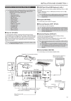
1 INSTALLATION AND CONNECTIOINNSTALLATION AND CONNECTION 1 Installation ● Do not lift this transceiver by holding the Tuning control or other control knobs on the front panel or the connectors on the rear panel. Doing so may result in injury or damage of the control knobs. Installation of Lightning Arrestors • To prevent fire, electric shock, malfunctioning and injury due to lightning, install a coaxial lightning arrestor. • Besides installing a coaxial lightning arrestor, disconnect the cable of the antenna from this transceiver if lightning is anticipated. Antenna Installation and Connection The antenna system is made up of the antenna, coaxial cables and a ground terminal. Installing the antenna system carefully and properly helps to optimize the performance of the transceiver. • Make use of a correctly-adjusted 50 Ω antenna, 50 Ω coaxial cables and appropriate connectors. Make sure that all connections are cleaned and free of dirt before fastening them. • Match the impedance of the coaxial cable and antenna such that SWR is 1:1.5 or lower. • A high SWR may lower the TX output power, thereby causing radio interference with electrical appliances such as radio and TV as well as failure of this transceiver. • If reports on signal distortion are received, this means the transceiver may not be transmitting efficiently. ● Transmitting without connecting the antenna may damage this transceiver. Before transmission, connect an antenna or a 50 Ω dummy load to this transceiver. ● The protection circuit of this transceiver will be activated if the SWR of the antenna exceeds 1.5. Use an antenna with a low SWR. ● When an RX antenna that makes use of semiconductors (such as an active antenna) is connected, transmission or antenna tuning must not be performed. Doing so supplies power to the antenna and may damage the semiconductor circuit of the antenna. Connection of Regulated DC Power Supply ● Make sure to turn off the power of the regulated DC power supply before connecting the DC power cord. ● Do not insert the power plug of the regulated DC power supply into the AC outlet until all the connections are complete. A DC 13.8 V regulated DC power supply is needed for using this transceiver. It cannot be connected directly to an AC outlet. Use the supplied DC power cord to connect this transceiver to the regulated DC power supply. • The current capacity needed for the regulated DC power supply is 22.5 A and above. Use one with sufficient current capacity. 1 Connect the DC power cord to the regulated DC power supply. Connect the red wire to the "+" terminal and the black wire to the "-" terminal. 2 Next, connect the DC power cord to the DC 13.8 V power connector of this transceiver. Insert the cord fully into the power connector. Using the Auxiliary Support An auxiliary support is stored inside the front leg of this transceiver. Pull it toward you if you want the panel to face slightly upwards. Ground Connection Connect to the ground terminal correctly to avoid risks such as electric shock. First of all, bury one or multiple ground bars or a large copper sheet in the ground and connect them to the GND terminal of this transceiver. Use a thick conducting wire or a cut copper band that is as short as possible for this connection. ● Gas pipes, conduit pipes for power distribution, plastic water pipes and the like must not be used for grounding. Not only are they ineffective for grounding, they may also result in accidents or fire. DC Power Cord Fuse Black (-) Red (+) .. Rear Side of This Transceiver Regulated DC Power Supply 1-1
-
 1
1 -
2
-
3
-
4
-
5
-
6
-
7
-
 8
8 -
 9
9 -
 10
10 -
 11
11 -
 12
12 -
 13
13 -
 14
14 -
 15
15 -
 16
16 -
 17
17 -
 18
18 -
19
-
20
-
21
-
22
-
23
-
24
-
25
-
26
-
27
-
28
-
29
-
30
-
31
-
32
-
33
-
34
-
35
-
36
-
37
-
38
-
39
-
40
-
41
-
42
-
43
-
44
-
45
-
46
-
47
-
48
-
49
-
50
-
51
-
52
-
53
-
54
-
55
-
56
-
57
-
58
-
59
-
60
-
61
-
62
-
63
-
64
-
65
-
66
-
67
-
68
-
69
-
70
-
71
-
72
-
73
-
74
-
75
-
76
-
77
-
78
-
79
-
80
-
81
-
82
-
83
-
84
-
85
-
86
-
87
-
88
-
89
-
90
-
91
-
92
-
93
-
94
-
95
-
96
-
97
-
98
-
99
-
100
-
101
-
102
-
103
-
104
-
105
-
106
-
107
-
108
-
109
-
110
-
111
-
112
-
113
-
114
-
115
-
116
-
117
-
118
-
119
-
120
-
121
-
122
-
123
-
124
-
125
-
126
-
127
-
128
-
129
-
130
-
131
-
132
-
133
-
134
-
135
-
136
-
137
-
138
-
139
-
140
-
141
-
142
-
143
-
144
-
145
-
146
-
147
-
148
-
149
-
150
-
151
-
152
-
153
-
154
-
155
-
156
-
157
-
158
-
159
-
160
-
161
-
162
-
163
-
164
-
165
-
166
-
167
-
168
-
169
-
170
-
171
-
172
-
173
-
174
-
175
-
176
-
177
-
178
-
179
-
180
-
181
-
182
-
183
-
184
-
185
-
186
-
187
-
188
-
189
-
190
-
191
-
192
-
193
-
194
-
195
-
196
 |
 |
