Kenwood TS-890S Operation Manual - Page 19
ACC 2 Connector
 |
View all Kenwood TS-890S manuals
Add to My Manuals
Save this manual to your list of manuals |
Page 19 highlights
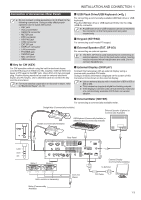
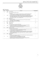
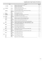
INSTALLATION AND CONNECTION 1 . ACC 2 Connector Pin No. - 2 3 4 5 6 7 8 9 10 11 12 13 Pin Name NC RTTY ANO GND PSQ MET 1 NC GND PKS MET2 ANI GND SS Function No connection RTTY control terminal (FSK key input) Audio output • Connect to the audio input of a PC or an external device such as a PC connection interface. • The audio output level is independent of the AF volume control knob on the front panel. • The audio output level can be adjusted in Menu [7-09]. Adjust it to an appropriate level. • When the audio output level is configured to the default value of "50" in Menu [7-09], the peak-to- peak voltage is approximately 0.5 V p-p in the case of standard modulation signals. Altering the audio output level between "0" and "100" changes the peak-to-peak voltage level between approximately 0 Vp-p and 1.2 Vp-p. (Impedance 10 kΩ) Signal ground Squelch control output • Connect to the squelch input of an external device such as a PC connection interface. • When squelch is open: Low impedance • When squelch is closed: High impedance Meter level output 1 No connection Signal ground PTT input for data communication (DATA SEND) • Connect to the PTT output of an external device such as a PC connection interface. • Signal can be transmitted by connecting the PKS terminal to GND. • The PKS terminal mutes unnecessary modulation input signals during transmission. Refer to Configuration of the Input Path of TX Audio (8-1). Meter level output 2 Audio input for data communication • Connect to the audio output of a PC or an external device such as a PC connection interface. • The audio input level is independent of MIC GAIN on the front panel. • The audio input level can be adjusted in Menu [7-07]. • Standard modulation can be obtained with an input of approximately 10 mVrms in the default setting of "50" in Menu [7-09]. Altering the audio input level between "0" and "100" changes the standard modulation input level between approximately "almost no modulation" and approx. 1 mVrms. (Impedance 10 kΩ) Signal ground PTT input • This is the same terminal as pin 2 (SS terminal) of the MIC connector on the front panel and pin 3 (SS terminal) of the REMOTE connector. • It has the same behavior as pressing [SEND] on the front panel. • Signal can be transmitted by connecting the SS terminal to GND. • The SS terminal mutes unnecessary modulation input signals during transmission. Refer to Configuration of the Input Path of TX Audio (8-1). Input/Output - I O - O O - - I O I - I 1-7
-
 1
1 -
2
-
3
-
4
-
5
-
6
-
7
-
8
-
9
-
10
-
11
-
12
-
13
-
 14
14 -
 15
15 -
 16
16 -
 17
17 -
 18
18 -
 19
19 -
 20
20 -
 21
21 -
 22
22 -
 23
23 -
 24
24 -
25
-
26
-
27
-
28
-
29
-
30
-
31
-
32
-
33
-
34
-
35
-
36
-
37
-
38
-
39
-
40
-
41
-
42
-
43
-
44
-
45
-
46
-
47
-
48
-
49
-
50
-
51
-
52
-
53
-
54
-
55
-
56
-
57
-
58
-
59
-
60
-
61
-
62
-
63
-
64
-
65
-
66
-
67
-
68
-
69
-
70
-
71
-
72
-
73
-
74
-
75
-
76
-
77
-
78
-
79
-
80
-
81
-
82
-
83
-
84
-
85
-
86
-
87
-
88
-
89
-
90
-
91
-
92
-
93
-
94
-
95
-
96
-
97
-
98
-
99
-
100
-
101
-
102
-
103
-
104
-
105
-
106
-
107
-
108
-
109
-
110
-
111
-
112
-
113
-
114
-
115
-
116
-
117
-
118
-
119
-
120
-
121
-
122
-
123
-
124
-
125
-
126
-
127
-
128
-
129
-
130
-
131
-
132
-
133
-
134
-
135
-
136
-
137
-
138
-
139
-
140
-
141
-
142
-
143
-
144
-
145
-
146
-
147
-
148
-
149
-
150
-
151
-
152
-
153
-
154
-
155
-
156
-
157
-
158
-
159
-
160
-
161
-
162
-
163
-
164
-
165
-
166
-
167
-
168
-
169
-
170
-
171
-
172
-
173
-
174
-
175
-
176
-
177
-
178
-
179
-
180
-
181
-
182
-
183
-
184
-
185
-
186
-
187
-
188
-
189
-
190
-
191
-
192
-
193
-
194
-
195
-
196
 |
 |
