Kenwood TS-890S Operation Manual - Page 27
Rear Panel
 |
View all Kenwood TS-890S manuals
Add to My Manuals
Save this manual to your list of manuals |
Page 27 highlights
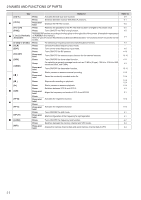
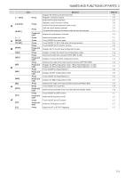
Rear Panel NAMES AND FUNCTIONS OF PARTS 2 Connectors and Jacks on the Rear Panel No. Name Connector Connector Connector Connector Connector Connector Connector Jack Connector Connector Connector Jack Terminal Connector Connector Jack Connector Connector Connector Connector Terminal Description Remarks M-type coaxial connector for connecting the antenna. For input of 10 MHz signals when using an external reference frequency. For connecting a regulated DC power supply. • Input impedance: 50 Ω • Input: 0 dBm ±10 dB Connector for connecting a USB flash drive or USB keyboard. RS-232C connector for connecting a PC or external device. Connector for controlling an external antenna tuner. For connecting an external speaker. Connector for connecting a PC or LAN when running with the KNS (KENWOOD NETWORK COMMAND SYSTEM) or for automatic correction of the clock time. DVI-I connector for connecting an external monitor. Both analog and digital signals can be output. Connector for connecting a PC. It is used to control this transceiver using the ARCP-890 as well as to input and output signals for transmission and reception via the digital communication application of a PC. It can be switched between transmission and reception by changing the menu setting and keying. For connecting an electronic key (straight key, bug key, external electronic key, etc.) when running in the CW mode. This can be configured to a jack for paddle connection in the menu. For connecting a commercially available meter. • Output impedance: 4.7 Ω • Allowable open-end voltage output: 0 to 5 V For connecting a linear amplifier. (Use the supplied 7-pin DIN plug for the connection.) For connecting an external device such as an auxiliary equipment for data communication. (Use the supplied 13-pin DIN plug for the connection.) For connecting a self-made PF keypad. For connecting a transverter or linear amplifier. For connecting devices such as an external receiver. • Output impedance: 50 Ω • Output: Approx. 1 mW (0 dBm) For connecting an RX antenna, external bandpass filter, transverter and the like. For connecting an external bandpass filter and the like. For connecting a ground wire. 2-7
-
 1
1 -
2
-
3
-
4
-
5
-
6
-
7
-
8
-
9
-
10
-
11
-
12
-
13
-
14
-
15
-
16
-
17
-
18
-
19
-
20
-
21
-
 22
22 -
 23
23 -
 24
24 -
 25
25 -
 26
26 -
 27
27 -
 28
28 -
 29
29 -
 30
30 -
 31
31 -
 32
32 -
33
-
34
-
35
-
36
-
37
-
38
-
39
-
40
-
41
-
42
-
43
-
44
-
45
-
46
-
47
-
48
-
49
-
50
-
51
-
52
-
53
-
54
-
55
-
56
-
57
-
58
-
59
-
60
-
61
-
62
-
63
-
64
-
65
-
66
-
67
-
68
-
69
-
70
-
71
-
72
-
73
-
74
-
75
-
76
-
77
-
78
-
79
-
80
-
81
-
82
-
83
-
84
-
85
-
86
-
87
-
88
-
89
-
90
-
91
-
92
-
93
-
94
-
95
-
96
-
97
-
98
-
99
-
100
-
101
-
102
-
103
-
104
-
105
-
106
-
107
-
108
-
109
-
110
-
111
-
112
-
113
-
114
-
115
-
116
-
117
-
118
-
119
-
120
-
121
-
122
-
123
-
124
-
125
-
126
-
127
-
128
-
129
-
130
-
131
-
132
-
133
-
134
-
135
-
136
-
137
-
138
-
139
-
140
-
141
-
142
-
143
-
144
-
145
-
146
-
147
-
148
-
149
-
150
-
151
-
152
-
153
-
154
-
155
-
156
-
157
-
158
-
159
-
160
-
161
-
162
-
163
-
164
-
165
-
166
-
167
-
168
-
169
-
170
-
171
-
172
-
173
-
174
-
175
-
176
-
177
-
178
-
179
-
180
-
181
-
182
-
183
-
184
-
185
-
186
-
187
-
188
-
189
-
190
-
191
-
192
-
193
-
194
-
195
-
196
 |
 |
