Kenwood TS-890S Operation Manual - Page 17
Configuration for Switching the RX Bandwidth
 |
View all Kenwood TS-890S manuals
Add to My Manuals
Save this manual to your list of manuals |
Page 17 highlights
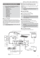
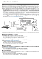
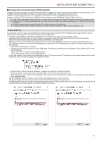
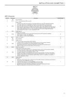
.. INSTALLATION AND CONNECTION 1 ■ Configuration for Switching the RX Bandwidth Configure the setting as follows to switch the RX bandwidth by cutting off the high or low frequencies within the frequency range of 0 Hz to 5000 Hz even in the SSB-DATA mode, in the same way as in SSB mode, during operations such as FT8. * Refer to "Configuring the Behavior of the HI/SHIFT and LO/WIDTH Controls (SSB/SSB-DATA Only)" (6-3). Configure in Menu [6-12] "Filter Control in SSB-DATA Mode (High/Low and Shift/Width)". Select "High & Low Cut". ● USB cable and RS-232C straight cable are not supplied with this transceiver. Please purchase commercially available cables. ● Delays may occur when using USB audio, and there may also be audio interruptions depending on the performance and load of the PC. ● Place this transceiver far enough from the PC so that noise will not be picked up. ● For data communication software settings, refer to the instruction manual or Help file of the software in use. Virtual COM Port PC command control using the virtual COM port and USB keying control using the RTS/DTR signal of the virtual COM port can be performed by connecting this transceiver and the PC using a USB cable. • To use the virtual COM port, Windows 10, Windows 8.1 or Windows 7 is required. (as of January, 2019) • Install the virtual COM port driver on the PC before connecting the USB cable. Download the driver from the following URL. http://www.kenwood.com/i/products/info/amateur/software_download.html • There are 2 types of virtual COM port on this transceiver, namely virtual COM (Standard) port and virtual COM (Enhanced) port. • The COM port numbers of the virtual COM (Standard) port and virtual COM (Enhanced) port on the PC can be checked using the following way. • Open the Device Manager in Windows. • Connect this transceiver and the PC using a USB cable. The following 2 COM ports are displayed in "Ports (COM & LPT)" in the Device Manager. "Silicon Labs CP210x USB to UART Bridge (COM x)" "Silicon Labs CP210x USB to UART Bridge (COM y)" x and y are numbers. The numbers vary depending on the PC environment used. The following is the display example of the virtual COM ports on this transceiver assigned to COM3 and COM4. • Double-click on these in the Device Manager to display the respective Properties windows. • Select the "Details" tab and then select "Location paths" from the Property drop-down menu. • Move the mouse cursor to the top line displayed in the "Value" column and check the number in the parenthesis on the right end of the character string. The port displayed with the number (1) is the virtual COM (Standard) port of this transceiver. The port displayed with the number (2) is the virtual COM (Enhanced) port of this transceiver. The following is the display example of the Properties window of each COM port when the virtual COM (Standard) port and the virtual COM (Enhanced) port are assigned to COM3 and COM4 respectively. 1-5
-
 1
1 -
2
-
3
-
4
-
5
-
6
-
7
-
8
-
9
-
10
-
11
-
 12
12 -
 13
13 -
 14
14 -
 15
15 -
 16
16 -
 17
17 -
 18
18 -
 19
19 -
 20
20 -
 21
21 -
 22
22 -
23
-
24
-
25
-
26
-
27
-
28
-
29
-
30
-
31
-
32
-
33
-
34
-
35
-
36
-
37
-
38
-
39
-
40
-
41
-
42
-
43
-
44
-
45
-
46
-
47
-
48
-
49
-
50
-
51
-
52
-
53
-
54
-
55
-
56
-
57
-
58
-
59
-
60
-
61
-
62
-
63
-
64
-
65
-
66
-
67
-
68
-
69
-
70
-
71
-
72
-
73
-
74
-
75
-
76
-
77
-
78
-
79
-
80
-
81
-
82
-
83
-
84
-
85
-
86
-
87
-
88
-
89
-
90
-
91
-
92
-
93
-
94
-
95
-
96
-
97
-
98
-
99
-
100
-
101
-
102
-
103
-
104
-
105
-
106
-
107
-
108
-
109
-
110
-
111
-
112
-
113
-
114
-
115
-
116
-
117
-
118
-
119
-
120
-
121
-
122
-
123
-
124
-
125
-
126
-
127
-
128
-
129
-
130
-
131
-
132
-
133
-
134
-
135
-
136
-
137
-
138
-
139
-
140
-
141
-
142
-
143
-
144
-
145
-
146
-
147
-
148
-
149
-
150
-
151
-
152
-
153
-
154
-
155
-
156
-
157
-
158
-
159
-
160
-
161
-
162
-
163
-
164
-
165
-
166
-
167
-
168
-
169
-
170
-
171
-
172
-
173
-
174
-
175
-
176
-
177
-
178
-
179
-
180
-
181
-
182
-
183
-
184
-
185
-
186
-
187
-
188
-
189
-
190
-
191
-
192
-
193
-
194
-
195
-
196
 |
 |
