Lenovo ThinkCentre M92 Hardware Maintenance Manual (HMM) (May 2012) - ThinkCen - Page 135
The front fan assembly is attached to the chassis by four rubber mounts. Remove the front fan assembly
 |
View all Lenovo ThinkCentre M92 manuals
Add to My Manuals
Save this manual to your list of manuals |
Page 135 highlights
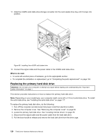
5. The front fan assembly is attached to the chassis by four rubber mounts. Remove the front fan assembly by breaking or cutting the rubber mounts and gently pulling the front fan assembly out of the chassis. Note: The new front fan assembly will have four new rubber mounts attached. Figure 63. Removing the front fan assembly 6. Install the new front fan assembly by aligning the new rubber mounts with the corresponding holes in the chassis and push the rubber mounts through the holes. Chapter 9. Replacing FRUs (machine types: 2697, 2698, 2742, 2750, 2935, 2943, 2960, 2967, 2986, 2992, 2994, 2999, 3182, 3184, 3186, 3190, 3201, 3204, 3208, 3212, 3217, 3220, 3226, 3228, 3302, 3391, and 3392) 129
-
 1
1 -
2
-
3
-
4
-
5
-
6
-
7
-
8
-
9
-
10
-
11
-
12
-
13
-
14
-
15
-
16
-
17
-
18
-
19
-
20
-
21
-
22
-
23
-
24
-
25
-
26
-
27
-
28
-
29
-
30
-
31
-
32
-
33
-
34
-
35
-
36
-
37
-
38
-
39
-
40
-
41
-
42
-
43
-
44
-
45
-
46
-
47
-
48
-
49
-
50
-
51
-
52
-
53
-
54
-
55
-
56
-
57
-
58
-
59
-
60
-
61
-
62
-
63
-
64
-
65
-
66
-
67
-
68
-
69
-
70
-
71
-
72
-
73
-
74
-
75
-
76
-
77
-
78
-
79
-
80
-
81
-
82
-
83
-
84
-
85
-
86
-
87
-
88
-
89
-
90
-
91
-
92
-
93
-
94
-
95
-
96
-
97
-
98
-
99
-
100
-
101
-
102
-
103
-
104
-
105
-
106
-
107
-
108
-
109
-
110
-
111
-
112
-
113
-
114
-
115
-
116
-
117
-
118
-
119
-
120
-
121
-
122
-
123
-
124
-
125
-
126
-
127
-
128
-
129
-
 130
130 -
 131
131 -
 132
132 -
 133
133 -
 134
134 -
 135
135 -
 136
136 -
 137
137 -
 138
138 -
 139
139 -
 140
140 -
141
-
142
-
143
-
144
-
145
-
146
-
147
-
148
-
149
-
150
-
151
-
152
-
153
-
154
-
155
-
156
-
157
-
158
-
159
-
160
-
161
-
162
-
163
-
164
-
165
-
166
-
167
-
168
-
169
-
170
-
171
-
172
-
173
-
174
-
175
-
176
-
177
-
178
-
179
-
180
-
181
-
182
-
183
-
184
-
185
-
186
-
187
-
188
-
189
-
190
-
191
-
192
-
193
-
194
-
195
-
196
-
197
-
198
-
199
-
200
-
201
-
202
-
203
-
204
-
205
-
206
-
207
-
208
-
209
-
210
-
211
-
212
-
213
-
214
-
215
-
216
-
217
-
218
-
219
-
220
-
221
-
222
-
223
-
224
-
225
-
226
-
227
-
228
-
229
-
230
-
231
-
232
-
233
-
234
-
235
-
236
-
237
-
238
-
239
-
240
-
241
-
242
-
243
-
244
-
245
-
246
-
247
-
248
-
249
-
250
-
251
-
252
-
253
-
254
-
255
-
256
-
257
-
258
-
259
-
260
-
261
-
262
-
263
-
264
-
265
-
266
-
267
-
268
-
269
-
270
-
271
-
272
-
273
-
274
-
275
-
276
-
277
-
278
-
279
-
280
-
281
-
282
 |
 |

5. The front fan assembly is attached to the chassis by four rubber mounts. Remove the front fan assembly
by breaking or cutting the rubber mounts and gently pulling the front fan assembly out of the chassis.
Note:
The new front fan assembly will have four new rubber mounts attached.
Figure 63. Removing the front fan assembly
6. Install the new front fan assembly by aligning the new rubber mounts with the corresponding holes in
the chassis and push the rubber mounts through the holes.
Chapter 9
.
Replacing FRUs (machine types: 2697, 2698, 2742, 2750, 2935, 2943, 2960, 2967, 2986, 2992, 2994, 2999, 3182,
3184, 3186, 3190, 3201, 3204, 3208, 3212, 3217, 3220, 3226, 3228, 3302, 3391, and 3392)
129