Lenovo ThinkCentre M92 Hardware Maintenance Manual (HMM) (May 2012) - ThinkCen - Page 91
System board part locations on shows the locations of the parts on the other
 |
View all Lenovo ThinkCentre M92 manuals
Add to My Manuals
Save this manual to your list of manuals |
Page 91 highlights
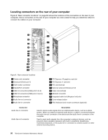
Figure 11 "System board part locations" on page 85 shows the locations of the parts on the other type of system board. Figure 11. System board part locations 1 4-pin microprocessor power connector 16 Front panel connector (for connecting LED indicators and power switch) 2 Microprocessor 17 Clear CMOS (Complementary Metal Oxide Semiconductor) /Recovery jumper 3 Microprocessor fan connector 18 Front USB connector 1 (for connecting USB ports 1 and 2 on the front bezel) 4 Memory slot 1 (DIMM 1) 19 Battery 5 Memory slot 2 (DIMM 2) 20 Front USB connector 2 (for connecting additional USB devices) 6 Memory slot 3 (DIMM 3) 21 Serial (COM2) connector 7 Memory slot 4 (DIMM 4) 22 Internal speaker connector 8 Thermal sensor connector 23 Front audio connector 9 4-pin SATA power connectors (2) 24 PCI card slots (2) 10 14-pin power connector 25 DisplayPort connector 11 SATA connector 1 (SATA 3.0 connector) 26 PCI Express x1 card slot 12 Parallel connector 27 PCI Express x16 graphics card slot 13 SATA connectors 2 and 3 (SATA 2.0 connectors) 28 System fan connector 14 eSATA connector 29 Cover presence switch connector (Intrusion switch connector) 15 Power fan connector 30 PS/2 keyboard and mouse connector Chapter 8. Locations 85
-
 1
1 -
2
-
3
-
4
-
5
-
6
-
7
-
8
-
9
-
10
-
11
-
12
-
13
-
14
-
15
-
16
-
17
-
18
-
19
-
20
-
21
-
22
-
23
-
24
-
25
-
26
-
27
-
28
-
29
-
30
-
31
-
32
-
33
-
34
-
35
-
36
-
37
-
38
-
39
-
40
-
41
-
42
-
43
-
44
-
45
-
46
-
47
-
48
-
49
-
50
-
51
-
52
-
53
-
54
-
55
-
56
-
57
-
58
-
59
-
60
-
61
-
62
-
63
-
64
-
65
-
66
-
67
-
68
-
69
-
70
-
71
-
72
-
73
-
74
-
75
-
76
-
77
-
78
-
79
-
80
-
81
-
82
-
83
-
84
-
85
-
 86
86 -
 87
87 -
 88
88 -
 89
89 -
 90
90 -
 91
91 -
 92
92 -
 93
93 -
 94
94 -
 95
95 -
 96
96 -
97
-
98
-
99
-
100
-
101
-
102
-
103
-
104
-
105
-
106
-
107
-
108
-
109
-
110
-
111
-
112
-
113
-
114
-
115
-
116
-
117
-
118
-
119
-
120
-
121
-
122
-
123
-
124
-
125
-
126
-
127
-
128
-
129
-
130
-
131
-
132
-
133
-
134
-
135
-
136
-
137
-
138
-
139
-
140
-
141
-
142
-
143
-
144
-
145
-
146
-
147
-
148
-
149
-
150
-
151
-
152
-
153
-
154
-
155
-
156
-
157
-
158
-
159
-
160
-
161
-
162
-
163
-
164
-
165
-
166
-
167
-
168
-
169
-
170
-
171
-
172
-
173
-
174
-
175
-
176
-
177
-
178
-
179
-
180
-
181
-
182
-
183
-
184
-
185
-
186
-
187
-
188
-
189
-
190
-
191
-
192
-
193
-
194
-
195
-
196
-
197
-
198
-
199
-
200
-
201
-
202
-
203
-
204
-
205
-
206
-
207
-
208
-
209
-
210
-
211
-
212
-
213
-
214
-
215
-
216
-
217
-
218
-
219
-
220
-
221
-
222
-
223
-
224
-
225
-
226
-
227
-
228
-
229
-
230
-
231
-
232
-
233
-
234
-
235
-
236
-
237
-
238
-
239
-
240
-
241
-
242
-
243
-
244
-
245
-
246
-
247
-
248
-
249
-
250
-
251
-
252
-
253
-
254
-
255
-
256
-
257
-
258
-
259
-
260
-
261
-
262
-
263
-
264
-
265
-
266
-
267
-
268
-
269
-
270
-
271
-
272
-
273
-
274
-
275
-
276
-
277
-
278
-
279
-
280
-
281
-
282
 |
 |
