Lenovo ThinkCentre M92 Hardware Maintenance Manual (HMM) (May 2012) - ThinkCen - Page 270
In most areas of the world, Lenovo requires the return of the defective Customer Replaceable Unit
 |
View all Lenovo ThinkCentre M92 manuals
Add to My Manuals
Save this manual to your list of manuals |
Page 270 highlights
4. Install the screw to secure the computer cover. Figure 229. Installing the computer cover screw 5. If there is an integrated cable lock available, lock the computer. 6. Reconnect the external cables and power cords to the computer. See "Locating connectors on the rear of your computer" on page 88. 7. To update your configuration, refer to Chapter 6 "Using the Setup Utility program" on page 59. Note: In most areas of the world, Lenovo requires the return of the defective Customer Replaceable Unit (CRU). Information about this will come with the CRU or will come a few days after the CRU arrives. 264 ThinkCentre Hardware Maintenance Manual
-
 1
1 -
2
-
3
-
4
-
5
-
6
-
7
-
8
-
9
-
10
-
11
-
12
-
13
-
14
-
15
-
16
-
17
-
18
-
19
-
20
-
21
-
22
-
23
-
24
-
25
-
26
-
27
-
28
-
29
-
30
-
31
-
32
-
33
-
34
-
35
-
36
-
37
-
38
-
39
-
40
-
41
-
42
-
43
-
44
-
45
-
46
-
47
-
48
-
49
-
50
-
51
-
52
-
53
-
54
-
55
-
56
-
57
-
58
-
59
-
60
-
61
-
62
-
63
-
64
-
65
-
66
-
67
-
68
-
69
-
70
-
71
-
72
-
73
-
74
-
75
-
76
-
77
-
78
-
79
-
80
-
81
-
82
-
83
-
84
-
85
-
86
-
87
-
88
-
89
-
90
-
91
-
92
-
93
-
94
-
95
-
96
-
97
-
98
-
99
-
100
-
101
-
102
-
103
-
104
-
105
-
106
-
107
-
108
-
109
-
110
-
111
-
112
-
113
-
114
-
115
-
116
-
117
-
118
-
119
-
120
-
121
-
122
-
123
-
124
-
125
-
126
-
127
-
128
-
129
-
130
-
131
-
132
-
133
-
134
-
135
-
136
-
137
-
138
-
139
-
140
-
141
-
142
-
143
-
144
-
145
-
146
-
147
-
148
-
149
-
150
-
151
-
152
-
153
-
154
-
155
-
156
-
157
-
158
-
159
-
160
-
161
-
162
-
163
-
164
-
165
-
166
-
167
-
168
-
169
-
170
-
171
-
172
-
173
-
174
-
175
-
176
-
177
-
178
-
179
-
180
-
181
-
182
-
183
-
184
-
185
-
186
-
187
-
188
-
189
-
190
-
191
-
192
-
193
-
194
-
195
-
196
-
197
-
198
-
199
-
200
-
201
-
202
-
203
-
204
-
205
-
206
-
207
-
208
-
209
-
210
-
211
-
212
-
213
-
214
-
215
-
216
-
217
-
218
-
219
-
220
-
221
-
222
-
223
-
224
-
225
-
226
-
227
-
228
-
229
-
230
-
231
-
232
-
233
-
234
-
235
-
236
-
237
-
238
-
239
-
240
-
241
-
242
-
243
-
244
-
245
-
246
-
247
-
248
-
249
-
250
-
251
-
252
-
253
-
254
-
255
-
256
-
257
-
258
-
259
-
260
-
261
-
262
-
263
-
264
-
 265
265 -
 266
266 -
 267
267 -
 268
268 -
 269
269 -
 270
270 -
 271
271 -
 272
272 -
 273
273 -
 274
274 -
 275
275 -
276
-
277
-
278
-
279
-
280
-
281
-
282
 |
 |

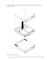
4. Install the screw to secure the computer cover.
Figure 229. Installing the computer cover screw
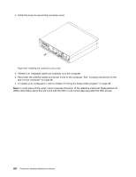
5. If there is an integrated cable lock available, lock the computer.
6. Reconnect the external cables and power cords to the computer. See “Locating connectors on the
rear of your computer” on page 88.
7. To update your configuration, refer to Chapter 6 “Using the Setup Utility program” on page 59.
Note:
In most areas of the world, Lenovo requires the return of the defective Customer Replaceable Unit
(CRU). Information about this will come with the CRU or will come a few days after the CRU arrives.
264
ThinkCentre Hardware Maintenance Manual