Lenovo ThinkCentre M92 Hardware Maintenance Manual (HMM) (May 2012) - ThinkCen - Page 145
Replacing the WiFi units, Removing the WiFi adapter card
 |
View all Lenovo ThinkCentre M92 manuals
Add to My Manuals
Save this manual to your list of manuals |
Page 145 highlights
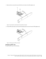
7. Position the new cover presence switch so that the screw hole in the cover presence switch is aligned with the corresponding hole in the chassis. Then install the screw to secure the cover presence switch to the chassis. Figure 73. Installing the new cover presence switch 8. Reconnect the cover presence switch cable to the system board. See "Locating parts on the system board" on page 75. 9. Reinstall the front bezel. See "Removing and reinstalling the front bezel" on page 95. What to do next: • To work with another piece of hardware, go to the appropriate section. • To complete the installation or replacement, go to "Completing the parts replacement" on page 150. Replacing the WiFi units Attention: Do not open your computer or attempt any repair before reading and understanding the "Important safety information" on page 1. This section provides instructions on how to replace the WiFi units. The WiFi units include a WiFi adapter card, a WiFi card module, and a rear WiFi antenna cable. Replacing the WiFi units involves the following operations: • "Removing the WiFi adapter card" on page 139 • "Removing the WiFi card module" on page 142 • "Installing the WiFi units" on page 143 Removing the WiFi adapter card To remove a WiFi adapter card, do the following: Chapter 9. Replacing FRUs (machine types: 2697, 2698, 2742, 2750, 2935, 2943, 2960, 2967, 2986, 2992, 2994, 2999, 3182, 3184, 3186, 3190, 3201, 3204, 3208, 3212, 3217, 3220, 3226, 3228, 3302, 3391, and 3392) 139
-
 1
1 -
2
-
3
-
4
-
5
-
6
-
7
-
8
-
9
-
10
-
11
-
12
-
13
-
14
-
15
-
16
-
17
-
18
-
19
-
20
-
21
-
22
-
23
-
24
-
25
-
26
-
27
-
28
-
29
-
30
-
31
-
32
-
33
-
34
-
35
-
36
-
37
-
38
-
39
-
40
-
41
-
42
-
43
-
44
-
45
-
46
-
47
-
48
-
49
-
50
-
51
-
52
-
53
-
54
-
55
-
56
-
57
-
58
-
59
-
60
-
61
-
62
-
63
-
64
-
65
-
66
-
67
-
68
-
69
-
70
-
71
-
72
-
73
-
74
-
75
-
76
-
77
-
78
-
79
-
80
-
81
-
82
-
83
-
84
-
85
-
86
-
87
-
88
-
89
-
90
-
91
-
92
-
93
-
94
-
95
-
96
-
97
-
98
-
99
-
100
-
101
-
102
-
103
-
104
-
105
-
106
-
107
-
108
-
109
-
110
-
111
-
112
-
113
-
114
-
115
-
116
-
117
-
118
-
119
-
120
-
121
-
122
-
123
-
124
-
125
-
126
-
127
-
128
-
129
-
130
-
131
-
132
-
133
-
134
-
135
-
136
-
137
-
138
-
139
-
 140
140 -
 141
141 -
 142
142 -
 143
143 -
 144
144 -
 145
145 -
 146
146 -
 147
147 -
 148
148 -
 149
149 -
 150
150 -
151
-
152
-
153
-
154
-
155
-
156
-
157
-
158
-
159
-
160
-
161
-
162
-
163
-
164
-
165
-
166
-
167
-
168
-
169
-
170
-
171
-
172
-
173
-
174
-
175
-
176
-
177
-
178
-
179
-
180
-
181
-
182
-
183
-
184
-
185
-
186
-
187
-
188
-
189
-
190
-
191
-
192
-
193
-
194
-
195
-
196
-
197
-
198
-
199
-
200
-
201
-
202
-
203
-
204
-
205
-
206
-
207
-
208
-
209
-
210
-
211
-
212
-
213
-
214
-
215
-
216
-
217
-
218
-
219
-
220
-
221
-
222
-
223
-
224
-
225
-
226
-
227
-
228
-
229
-
230
-
231
-
232
-
233
-
234
-
235
-
236
-
237
-
238
-
239
-
240
-
241
-
242
-
243
-
244
-
245
-
246
-
247
-
248
-
249
-
250
-
251
-
252
-
253
-
254
-
255
-
256
-
257
-
258
-
259
-
260
-
261
-
262
-
263
-
264
-
265
-
266
-
267
-
268
-
269
-
270
-
271
-
272
-
273
-
274
-
275
-
276
-
277
-
278
-
279
-
280
-
281
-
282
 |
 |
