Lenovo ThinkCentre M92 Hardware Maintenance Manual (HMM) (May 2012) - ThinkCen - Page 205
This provides instructions on how to replace the front audio and USB assembly.
 |
View all Lenovo ThinkCentre M92 manuals
Add to My Manuals
Save this manual to your list of manuals |
Page 205 highlights
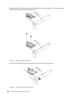
Figure 144. Installing the new internal speaker 9. Reconnect the internal speaker cable to the system board. See "Locating parts on the system board" on page 83. 10. Reinstall the cover presence switch. See "Replacing the cover presence switch" on page 195. 11. Reinstall the front bezel. See "Removing and reinstalling the front bezel" on page 154. What to do next: • To work with another piece of hardware, go to the appropriate section. • To complete the installation or replacement, go to "Completing the parts replacement" on page 210. Replacing the front audio and USB assembly Attention: Do not open your computer or attempt any repair before reading and understanding the "Important safety information" on page 1. This section provides instructions on how to replace the front audio and USB assembly. To replace the front audio and USB assembly, do the following: 1. Remove all media from the drives and turn off all attached devices and the computer. Then, disconnect all power cords from electrical outlets and disconnect all cables that are connected to the computer. Chapter 10. Replacing FRUs (machine types: 2756, 2800, 2929, 2932, 2934, 2941, 2945, 2961, 2982, 2988, 2993, 2996, 3181, 3183, 3185, 3187, 3198, 3202, 3207, 3209, 3214, 3218, 3224, 3227, 3306, 3393, and 3395) 199
-
 1
1 -
2
-
3
-
4
-
5
-
6
-
7
-
8
-
9
-
10
-
11
-
12
-
13
-
14
-
15
-
16
-
17
-
18
-
19
-
20
-
21
-
22
-
23
-
24
-
25
-
26
-
27
-
28
-
29
-
30
-
31
-
32
-
33
-
34
-
35
-
36
-
37
-
38
-
39
-
40
-
41
-
42
-
43
-
44
-
45
-
46
-
47
-
48
-
49
-
50
-
51
-
52
-
53
-
54
-
55
-
56
-
57
-
58
-
59
-
60
-
61
-
62
-
63
-
64
-
65
-
66
-
67
-
68
-
69
-
70
-
71
-
72
-
73
-
74
-
75
-
76
-
77
-
78
-
79
-
80
-
81
-
82
-
83
-
84
-
85
-
86
-
87
-
88
-
89
-
90
-
91
-
92
-
93
-
94
-
95
-
96
-
97
-
98
-
99
-
100
-
101
-
102
-
103
-
104
-
105
-
106
-
107
-
108
-
109
-
110
-
111
-
112
-
113
-
114
-
115
-
116
-
117
-
118
-
119
-
120
-
121
-
122
-
123
-
124
-
125
-
126
-
127
-
128
-
129
-
130
-
131
-
132
-
133
-
134
-
135
-
136
-
137
-
138
-
139
-
140
-
141
-
142
-
143
-
144
-
145
-
146
-
147
-
148
-
149
-
150
-
151
-
152
-
153
-
154
-
155
-
156
-
157
-
158
-
159
-
160
-
161
-
162
-
163
-
164
-
165
-
166
-
167
-
168
-
169
-
170
-
171
-
172
-
173
-
174
-
175
-
176
-
177
-
178
-
179
-
180
-
181
-
182
-
183
-
184
-
185
-
186
-
187
-
188
-
189
-
190
-
191
-
192
-
193
-
194
-
195
-
196
-
197
-
198
-
199
-
 200
200 -
 201
201 -
 202
202 -
 203
203 -
 204
204 -
 205
205 -
 206
206 -
 207
207 -
 208
208 -
 209
209 -
 210
210 -
211
-
212
-
213
-
214
-
215
-
216
-
217
-
218
-
219
-
220
-
221
-
222
-
223
-
224
-
225
-
226
-
227
-
228
-
229
-
230
-
231
-
232
-
233
-
234
-
235
-
236
-
237
-
238
-
239
-
240
-
241
-
242
-
243
-
244
-
245
-
246
-
247
-
248
-
249
-
250
-
251
-
252
-
253
-
254
-
255
-
256
-
257
-
258
-
259
-
260
-
261
-
262
-
263
-
264
-
265
-
266
-
267
-
268
-
269
-
270
-
271
-
272
-
273
-
274
-
275
-
276
-
277
-
278
-
279
-
280
-
281
-
282
 |
 |
