Lenovo ThinkCentre M92 Hardware Maintenance Manual (HMM) (May 2012) - ThinkCen - Page 193
You might also need to release the power supply assembly cables from some cable clips or ties
 |
View all Lenovo ThinkCentre M92 manuals
Add to My Manuals
Save this manual to your list of manuals |
Page 193 highlights
6. Pivot the optical drive upward and disconnect the power supply assembly cables from all drives and from power connectors 1 , 2 and 3 on the system board. Figure 130. Power connectors on the system board Note: You might also need to release the power supply assembly cables from some cable clips or ties that secure the cables to the chassis. Ensure that you note the cable routing before disconnecting the cables. Chapter 10. Replacing FRUs (machine types: 2756, 2800, 2929, 2932, 2934, 2941, 2945, 2961, 2982, 2988, 2993, 2996, 3181, 3183, 3185, 3187, 3198, 3202, 3207, 3209, 3214, 3218, 3224, 3227, 3306, 3393, and 3395) 187
-
 1
1 -
2
-
3
-
4
-
5
-
6
-
7
-
8
-
9
-
10
-
11
-
12
-
13
-
14
-
15
-
16
-
17
-
18
-
19
-
20
-
21
-
22
-
23
-
24
-
25
-
26
-
27
-
28
-
29
-
30
-
31
-
32
-
33
-
34
-
35
-
36
-
37
-
38
-
39
-
40
-
41
-
42
-
43
-
44
-
45
-
46
-
47
-
48
-
49
-
50
-
51
-
52
-
53
-
54
-
55
-
56
-
57
-
58
-
59
-
60
-
61
-
62
-
63
-
64
-
65
-
66
-
67
-
68
-
69
-
70
-
71
-
72
-
73
-
74
-
75
-
76
-
77
-
78
-
79
-
80
-
81
-
82
-
83
-
84
-
85
-
86
-
87
-
88
-
89
-
90
-
91
-
92
-
93
-
94
-
95
-
96
-
97
-
98
-
99
-
100
-
101
-
102
-
103
-
104
-
105
-
106
-
107
-
108
-
109
-
110
-
111
-
112
-
113
-
114
-
115
-
116
-
117
-
118
-
119
-
120
-
121
-
122
-
123
-
124
-
125
-
126
-
127
-
128
-
129
-
130
-
131
-
132
-
133
-
134
-
135
-
136
-
137
-
138
-
139
-
140
-
141
-
142
-
143
-
144
-
145
-
146
-
147
-
148
-
149
-
150
-
151
-
152
-
153
-
154
-
155
-
156
-
157
-
158
-
159
-
160
-
161
-
162
-
163
-
164
-
165
-
166
-
167
-
168
-
169
-
170
-
171
-
172
-
173
-
174
-
175
-
176
-
177
-
178
-
179
-
180
-
181
-
182
-
183
-
184
-
185
-
186
-
187
-
 188
188 -
 189
189 -
 190
190 -
 191
191 -
 192
192 -
 193
193 -
 194
194 -
 195
195 -
 196
196 -
 197
197 -
 198
198 -
199
-
200
-
201
-
202
-
203
-
204
-
205
-
206
-
207
-
208
-
209
-
210
-
211
-
212
-
213
-
214
-
215
-
216
-
217
-
218
-
219
-
220
-
221
-
222
-
223
-
224
-
225
-
226
-
227
-
228
-
229
-
230
-
231
-
232
-
233
-
234
-
235
-
236
-
237
-
238
-
239
-
240
-
241
-
242
-
243
-
244
-
245
-
246
-
247
-
248
-
249
-
250
-
251
-
252
-
253
-
254
-
255
-
256
-
257
-
258
-
259
-
260
-
261
-
262
-
263
-
264
-
265
-
266
-
267
-
268
-
269
-
270
-
271
-
272
-
273
-
274
-
275
-
276
-
277
-
278
-
279
-
280
-
281
-
282
 |
 |

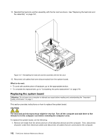
6. Pivot the optical drive upward and disconnect the power supply assembly cables from all drives and
from power connectors
1
,
2
and
3
on the system board.
Figure 130. Power connectors on the system board
Note:
You might also need to release the power supply assembly cables from some cable clips or ties
that secure the cables to the chassis. Ensure that you note the cable routing before disconnecting
the cables.
Chapter 10
.
Replacing FRUs (machine types: 2756, 2800, 2929, 2932, 2934, 2941, 2945, 2961, 2982, 2988, 2993, 2996, 3181,
3183, 3185, 3187, 3198, 3202, 3207, 3209, 3214, 3218, 3224, 3227, 3306, 3393, and 3395)
187