Pioneer DJM 400 Owner's Manual - Page 6
Names And Functions Of Parts - sampler
 |
UPC - 012562796543
View all Pioneer DJM 400 manuals
Add to My Manuals
Save this manual to your list of manuals |
Page 6 highlights
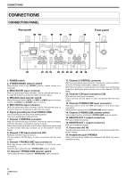
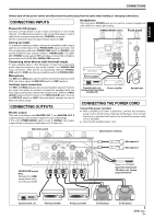
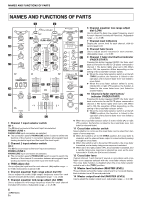
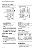
NAMES AND FUNCTIONS OF PARTS NAMES AND FUNCTIONS OF PARTS 1 2 POWER 6 Channel equalizer low-range adjust MIC MIC 1 LEVEL CD 1 PHONO 1 /LINE 1 TRIM CD 2 PHONO 2 /LINE 2 TRIM MASTER LEVEL 13 dial (LOW) Use to adjust the bass (low-range) frequency sound for each channel (includes kill function). (Adjustable 24 3 2 CHANNEL DJ MIXER 3 14 range: -∞ to +9 dB) 0 0 7 Channel level indicators MIC 2 LEVEL + 9 BEAT EFFECTS + 9 Display the current level for each channel, with 0.6 25 4 HI 4 HI 15 second peak hold. MASTER BPM LEVEL 8 Channel fader levers 0 AUTO EQ OVER + 9 OVER + 9 1 12 16 Use to adjust sound volumes for each channel. 26 5 MID 4 2 5 4 MID 2 (Adjustable range: -∞ to 0 dB) TAP 2 34 EQ 0 0 EQ 17 9 Channel 1 fader start button/indicator LOW HI -2 -2 4 11 (FADER START) MIC 27 + 9 6 LOW -4 -10 + 9 6 -4 LOW -10 BEAT PITCH 8 21 ERASE Pressing this button toggles ON/OFF, the fader start/ back cue function for the DJ CD player connected to OFF ON TALK OVER dB dB + 9 7 16 41 + 9 BEAT BANK 18 channel 1. The button lights when set to ON. When set to ON, the operation differs depending on the 19 setting of the cross fader selector switch. HEADPHONES CH-1 CH-2 MASTER 28 29 LEVEL 0 FADER START 9 10 9 8 7 8 6 5 4 3 2 1 0 THRU 10 9 8 7 86 5 4 3 2 1 0 11 FLANGER FILTER ECHO DELAY PHASER ROBOT ROLL IN-LOOP SAMPLER CH. SELECT 2 MIC 1 MASTER 10 FADER START LEVEL/DEPTH MIN MAX ON/OFF 20 21 22 23 ¶ When the cross fader selector switch is at the left (THRU) position, the function is linked to the operation of the channel fader lever (not linked to cross fader). ¶ When the cross fader selector switch is at the middle ( ) or right ( ) position, the function is linked to the cross fader lever (not linked to channel fader). 10 Channel 2 fader start button/ indicator (FADER START) Pressing this button toggles ON/OFF, the fader start/ back cue function for the DJ CD player connected to channel 2. The button lights when set to ON. When set to ON, the operation differs depending on the setting of the cross fader selector switch. PHONES ¶ When the cross fader selector switch is at the left (THRU) position, the function is linked to the 30 12 operation of the channel fader lever (not linked to cross fader). 1 Channel 1 input selector switch CD 1: ¶ When the cross fader selector switch is at the middle ( ) or right ( ) position, the function is linked to the cross fader lever (not linked to channel fader). The CD input connectors (line level input) are selected. PHONO 1/LINE 1: PHONO/LINE input connectors are selected. ¶ The connection panel's PHONO/LINE switch is used to switch the function of the channel 1 connectors between phonograph input (analog turntable input) and line input (line level input). 11 Cross fader selector switch Select whether or not to use the cross fader, and to select from two types of curve response. ¶ When the switch is set to left (THRU) position, the cross fader is disabled, and the channel fader output is mixed without passing through the cross fader. 2 Channel 2 input selector switch CD 2: The CD input connectors (line level input) are selected. PHONO 2/LINE 2: PHONO/LINE input connectors are selected. ¶ The connection panel's PHONO/LINE switch is used to switch the function of the channel 2 connectors between phonograph input (analog turntable input) and line input (line level input). 3 TRIM adjust dial Use to adjust the input level for each channel. (Adjustable range: -∞ to +9 dB, mid-position is about 0 dB) 4 Channel equalizer high-range adjust dial (HI) Use to adjust the treble (high-range) frequency sound for each channel (includes kill function). (Adjustable range: -∞ to +9 dB) 5 Channel equalizer mid-range adjust dial (MID) ¶ When this switch is set to the center ( ) position, the cross fader is enabled, and a slowly rising curve response is selected. ¶ When set to the right position ( ), the cross fader is enabled, and a rapidly rising curve response is selected (as soon as the lever leaves the [< 1] side, the [2 >] sound is heard). 12 Cross fader lever Outputs channel 1 and channel 2 sounds in accordance with cross fader curve response selected with the cross fader selector switch. The cross fader function is disabled when the cross fader selector switch is set to the [THRU] position. 13 Master level indicators (MASTER LEVEL) These indicators show the master output level in a monaural display. Each indicator has a 0.6 second peak hold. 14 Master output level dial (MASTER LEVEL) Use to adjust the master output level. (adjustable range: -∞ to 0 dB) Use to adjust the mid-range frequency sound for each channel (includes kill function). (Adjustable range: -∞ to +9 dB) 6 En
-
 1
1 -
 2
2 -
 3
3 -
 4
4 -
 5
5 -
 6
6 -
 7
7 -
 8
8 -
 9
9 -
 10
10 -
 11
11 -
 12
12 -
13
-
14
-
15
-
16
-
17
-
18
-
19
-
20
-
21
-
22
-
23
-
24
-
25
-
26
-
27
-
28
-
29
-
30
-
31
-
32
-
33
-
34
-
35
-
36
-
37
-
38
-
39
-
40
-
41
-
42
-
43
-
44
-
45
-
46
-
47
-
48
-
49
-
50
-
51
-
52
-
53
-
54
-
55
-
56
-
57
-
58
-
59
-
60
-
61
-
62
-
63
-
64
-
65
-
66
-
67
-
68
-
69
-
70
-
71
-
72
-
73
-
74
-
75
-
76
 |
 |
