Pioneer PDP-505HD Owner's Manual - Page 15
Connection to INPUT3 and INPUT4
 |
View all Pioneer PDP-505HD manuals
Add to My Manuals
Save this manual to your list of manuals |
Page 15 highlights
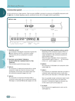
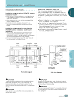
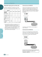
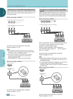
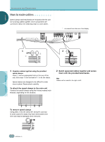
ENGLISH INSTALLATION AND CONNECTIONS C○o○nn○ec○ti○on○ t○o○IN○P○UT○3○a○nd○IN○ P○U○T4○ ○ Various components can be connected to the INPUT3 and INPUT4 jacks. After connections are made, on-screen setup is necessary to match the characteristics of the connected component. Please see pages 17 to 19 for on-screen setup after connection. ○ ○ ○ ○ ○ ○ ○ ○ ○ ○ ○ Connection to AV components Connection to AV component that has component video jacks Make component video connections for AV components with component video output capability. When connecting to INPUT3 ○ ○ INPUT3 [ON SYNC] jack G B [H/V SYNC] R HD VD Output source Video component/ personal computer (PC) with RGB output Y G ON SYNC CB/PB B CR/PR R G B R H/V SYNC ○ ○ ○ ○ ○ ○ ○ ○ ○ ○ ○ ○ Y CB/PB CR/PR G B R HD VD (ON SYNC) INPUT3 (H/V SYNC) 75Ωj2.2kΩ ○ ○ G Video component with component video output Y B R HD VD (CB/PB) (CR/PR) : Do not connect anything. : Connect to this jack. Note Components compatible with INPUT3 are also compatible with INPUT 4. When making connections to INPUT4, please refer to supplement 3 on page 57. For the screen sizes and input signals that INPUT3 and INPUT4 are compatible with, please refer to supplements 1 and 2 (pages 55 and 56). ○ ○ ○ ○ ○ ○ ○ ○ ○ ○ ○ ○ ○ ○ ○ ○ ○ ○ ○ ○ ○ On-screen setup is necessary after connection. Please see pages 17 and 18. INPUT3 jacks are all BNC jacks. If necessary, use Pin/BNC conversion adapters to make connections. When connecting to INPUT4 ○ ○ ○ ○ ○ ○ ○ ○ ○ ANALOG R G B INPUT4 INSTALLATION AND CONNECTIONS ○ ○ ○ ○ ○ ○ ○ ○ ○ ○ ○ ○ ○ ○ ○ ○ ○ ○ ○ ○ ○ ○ ○ ○ ○ On-screen setup is necessary after connection. Please see pages 17 and 18. 11 En ○
-
 1
1 -
2
-
3
-
4
-
5
-
6
-
7
-
8
-
9
-
 10
10 -
 11
11 -
 12
12 -
 13
13 -
 14
14 -
 15
15 -
 16
16 -
 17
17 -
 18
18 -
 19
19 -
 20
20 -
21
-
22
-
23
-
24
-
25
-
26
-
27
-
28
-
29
-
30
-
31
-
32
-
33
-
34
-
35
-
36
-
37
-
38
-
39
-
40
-
41
-
42
-
43
-
44
-
45
-
46
-
47
-
48
-
49
-
50
-
51
-
52
-
53
-
54
-
55
-
56
-
57
-
58
-
59
-
60
-
61
-
62
-
63
-
64
-
65
-
66
-
67
-
68
-
69
-
70
-
71
-
72
-
73
-
74
-
75
-
76
-
77
-
78
-
79
-
80
-
81
-
82
-
83
-
84
-
85
-
86
-
87
-
88
-
89
-
90
-
91
-
92
-
93
-
94
-
95
-
96
-
97
-
98
-
99
-
100
-
101
-
102
-
103
-
104
-
105
-
106
-
107
-
108
-
109
-
110
-
111
-
112
-
113
-
114
-
115
-
116
-
117
-
118
-
119
-
120
-
121
-
122
 |
 |
