Pioneer PDP-505HD Owner's Manual - Page 16
Connection of composite SYNC analog RGB, source, Connection of G ON SYNC analog RGB source - manuals
 |
View all Pioneer PDP-505HD manuals
Add to My Manuals
Save this manual to your list of manuals |
Page 16 highlights
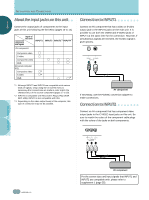
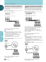
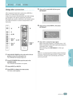
ENGLISH INSTALLATION AND CONNECTIONS ○ Connection of G ON SYNC analog RGB source Make G ON SYNC connections for an AV component with output that has the synchronization signal layered on top of the green signal. When connecting to INPUT3 ○ ○ ○ ○ ○ ○ ○ ○ ○ ○ Connection of composite SYNC analog RGB source Make composite SYNC connections for a component with output that has the vertical synchronization signal layered on top of the horizontal synchronization signal. When connecting to INPUT3 ○ ○ ○ ○ ○ ○ Y CB/PB CR/PR G B R HD VD (ON SYNC) INPUT3 (H/V SYNC) 75Ωj2.2kΩ ○ ○ Y CB/PB CR/PR G B R HD VD (ON SYNC) INPUT3 (H/V SYNC) 75Ω j 2.2kΩ ○ ○ ○ ○ ○ ○ ○ ○ ○ ○ ○ ○ ○ ○ ○ INSTALLATION AND CONNECTIONS On screen setup is necessary after connection. Please see pages 17 to 19. Notes ÷ When making G ON SYNC connections, do not make any connections to the VD or HD jacks. If connections are made, the picture may be not displayed normally. ÷ When using a computer connected by the G ON SYNC connection, on-screen adjustment for G ON SYNC is necessary (pages 17 to 19). Please read your PC's instruction manual throughly. When connecting to INPUT4 ANALOG R G B INPUT4 ○ ○ ○ ○ ○ ○ ○ ○ ○ ○ ○ ○ ○ ○ ○ ○ ○ ○ ○ ○ ○ ○ ○ ○ ○ ○ ○ ○ ○ ○ ○ ○ ○ When using INPUT3, set the impedance selector switch to match the output impedance of the connected component's synchronization signal. When the output impedance of the component's synchronization signal is above 75 Ω, set this switch to the 2.2 kΩ position. On-screen setup is necessary after connection. Please see pages 17 to 19. Notes ÷ When making composite SYNC connections, do not connect anything to the VD jack. If connected to, the picture may not be displayed properly. ÷ On some types of Macintosh® components, G ON SYNC and composite SYNC are both output. With this type of component, please connect using the G ON SYNC connection (as shown left). When connecting to INPUT4 ANALOG R G B INPUT4 ○ ○ ○ ○ ○ ○ ○ ○ ○ ○ ○ ○ ○ ○ On screen setup is necessary after connection. Please see pages 17 to 19. 12 En ○ ○ On-screen setup is necessary after connection. Please see pages 17 to 19.
-
 1
1 -
2
-
3
-
4
-
5
-
6
-
7
-
8
-
9
-
10
-
 11
11 -
 12
12 -
 13
13 -
 14
14 -
 15
15 -
 16
16 -
 17
17 -
 18
18 -
 19
19 -
 20
20 -
 21
21 -
22
-
23
-
24
-
25
-
26
-
27
-
28
-
29
-
30
-
31
-
32
-
33
-
34
-
35
-
36
-
37
-
38
-
39
-
40
-
41
-
42
-
43
-
44
-
45
-
46
-
47
-
48
-
49
-
50
-
51
-
52
-
53
-
54
-
55
-
56
-
57
-
58
-
59
-
60
-
61
-
62
-
63
-
64
-
65
-
66
-
67
-
68
-
69
-
70
-
71
-
72
-
73
-
74
-
75
-
76
-
77
-
78
-
79
-
80
-
81
-
82
-
83
-
84
-
85
-
86
-
87
-
88
-
89
-
90
-
91
-
92
-
93
-
94
-
95
-
96
-
97
-
98
-
99
-
100
-
101
-
102
-
103
-
104
-
105
-
106
-
107
-
108
-
109
-
110
-
111
-
112
-
113
-
114
-
115
-
116
-
117
-
118
-
119
-
120
-
121
-
122
 |
 |
