Pioneer PRO-1130HD Owner's Manual - Page 14
Standby/on, Tv Guide, Input, Enter, Volume Up/down, Up/down, Channel Up/down, Right, Eject - inputs
 |
View all Pioneer PRO-1130HD manuals
Add to My Manuals
Save this manual to your list of manuals |
Page 14 highlights
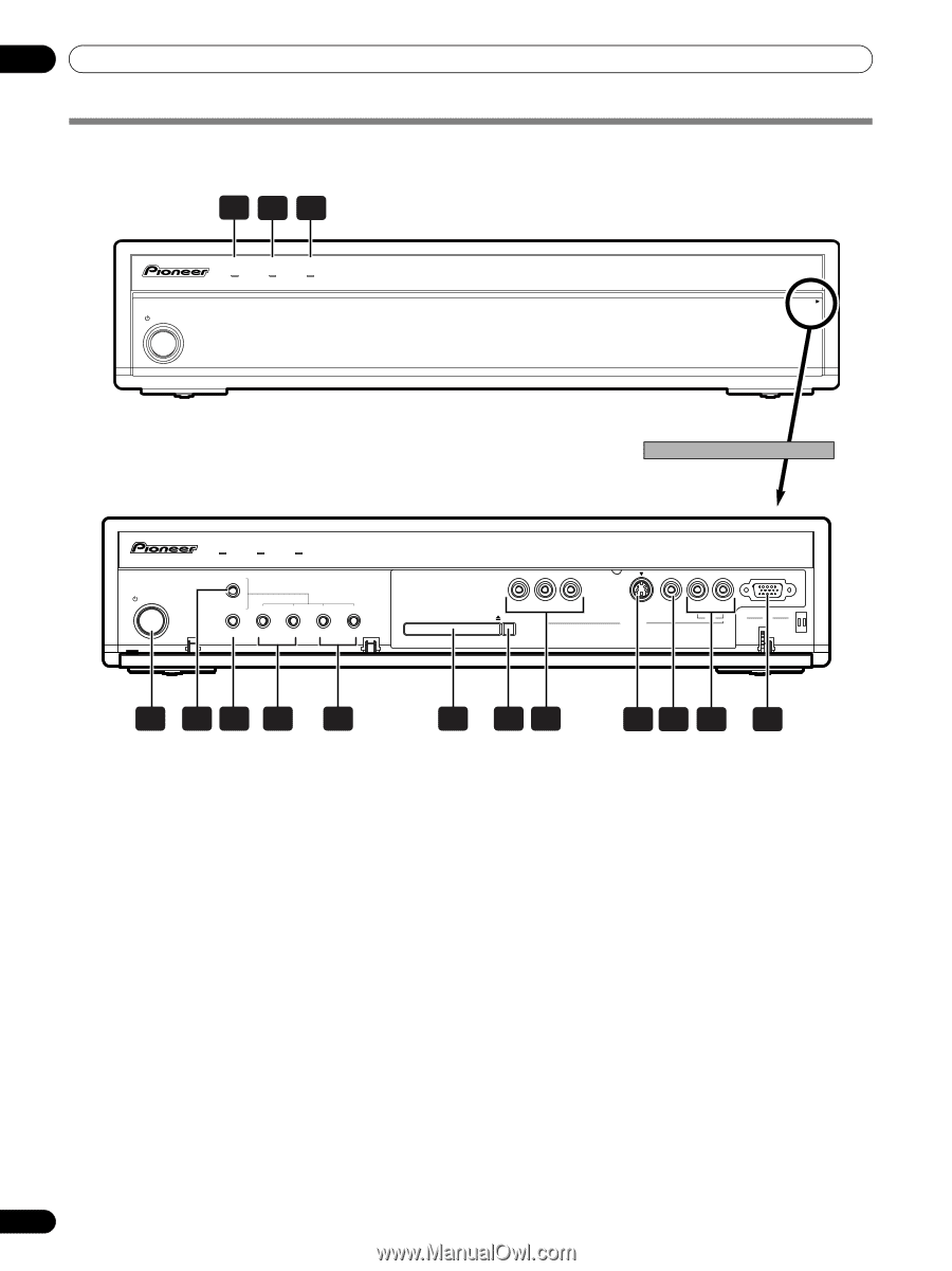
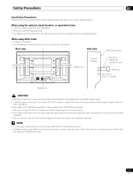
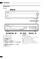
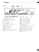
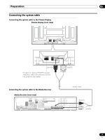
04 Part Names Media Receiver Front view 123 STANDBY/ON REC ON STANDBY TIMER PULL OPEN Pull this section to open the door. STANDBY/ON REC ON STANDBY TIMER TV GUIDE ENTER DOWN UP LEFT RIGHT INPUT DOWN UP VOLUME DOWN UP CHANNEL HOME GALLERY PC CARD SLOT Y CB / PB CR / PR COMPONENT VIDEO EJECT S-VIDEO VIDEO INPUT 4 L AUDIO R PC ANALOG RGB PC 4 56 7 8 9 1 POWER ON indicator 2 STANDBY indicator 3 REC TIMER indicator 4 STANDBY/ON button 5 TV GUIDE button* 6 INPUT button (ENTER button*) 7 VOLUME UP/DOWN buttons (UP/DOWN buttons*) 8 CHANNEL UP/DOWN buttons (LEFT/ RIGHT buttons*) 9 PC CARD slot 10 11 12 13 14 15 10 EJECT button 11 INPUT 4 terminals (COMPONENT VIDEO: Y, CB/PB, CR/PR) 12 INPUT 4 terminal (S-VIDEO) 13 INPUT 4 terminal (VIDEO) 14 INPUT 4/PC terminals (AUDIO) 15 PC INPUT terminal (ANALOG RGB) The buttons with asterisks (*) can operate the TV Guide On Screen™ system. 14 En
-
 1
1 -
2
-
3
-
4
-
5
-
6
-
7
-
8
-
 9
9 -
 10
10 -
 11
11 -
 12
12 -
 13
13 -
 14
14 -
 15
15 -
 16
16 -
 17
17 -
 18
18 -
 19
19 -
20
-
21
-
22
-
23
-
24
-
25
-
26
-
27
-
28
-
29
-
30
-
31
-
32
-
33
-
34
-
35
-
36
-
37
-
38
-
39
-
40
-
41
-
42
-
43
-
44
-
45
-
46
-
47
-
48
-
49
-
50
-
51
-
52
-
53
-
54
-
55
-
56
-
57
-
58
-
59
-
60
-
61
-
62
-
63
-
64
-
65
-
66
-
67
-
68
-
69
-
70
-
71
-
72
-
73
-
74
-
75
-
76
-
77
-
78
-
79
-
80
-
81
-
82
-
83
-
84
-
85
-
86
-
87
-
88
-
89
-
90
-
91
-
92
-
93
-
94
-
95
-
96
-
97
-
98
-
99
-
100
 |
 |