RCA HD61LPW42 User Guide & Warranty - Page 12
How to Connect: TV + VCR + DVD Player, Go
 |
UPC - 034909312742
View all RCA HD61LPW42 manuals
Add to My Manuals
Save this manual to your list of manuals |
Page 12 highlights
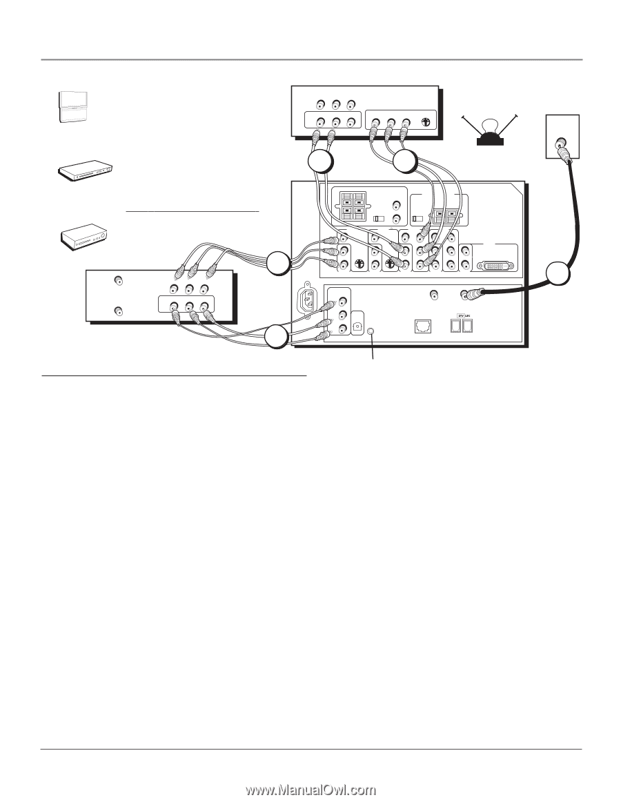
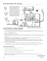
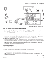
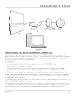
Connections & Setup POWER VOL + VOL - CH MENU CH TV DVD Note for U.S. Customers: If you prefer, we can provide you with the name of an Authorized Service Representative who will visit your home for a fee to install your electronic entertainment system and to instruct you in its operation. For details about this service, call 1-888-206-3359. For additional assistance while using your RCA product, please visit www.rca.com/customer support. VCR VCR ANTENNA IN ANTENNA OUT VIDEO OUT VIDEO IN L AUDIO R L AUDIO R 3A 3B R AUDIO L IN OUT R AUDIO L VIDEO VIDEO DVD PR PB Y S-VIDEO 2 2 OR OFF-AIR ANTENNA RIGHT LEFT FIXED/VARIABLE AUDIO OUTPUT SPEAKER SELECT INT W/ R EXT EXT SURR CENTER CHANNEL INPUT INTERNAL SPEAKER SOURCE EXTERNAL AMPLIFIER MAXIMUM POWER RATING! (60 WATTS into 8 OHMS) TV EXT AMP EXTERNAL SPEAKERS VIDEO INPUT 1 L VIDEO INPUT 2 VIDEO INPUT 3 VIDEO INPUT 4 V V V PR V PR L/MONO S-VIDEO L/MONO S-VIDEO L/MONO PB L/MONO PB L/MONO R AUDIO INPUT 1 R AUDIO INPUT 2 R AUDIO INPUT 3 YR AUDIO INPUT 4 YR AUDIO INPUT 5 TV VIDEO INPUT 5 DVI-HDTV RECORD OUTPUT VIDEO AUDIO R L DIGITAL AUDIO OUTPUT G-LINK ANTENNA B INPUT ETHERNET ANTENNA A INPUT CABLE 1 How to Connect: TV + VCR + DVD Player Connect G-LINK Cable (see page 23) 1. Connect your cable or off-air signal to ANTENNA A. If you have cable and an off-air antenna, connect the cable signal to ANTENNA A INPUT (antenna A is the only source for the GUIDE Plus+ system). Connect the off-air antenna to ANTENNA B INPUT. If you have only an off-air antenna, connect it to ANTENNA A INPUT. 2. Connect your DVD Player to your TV. Connect the DVD player's component (Y P P ) and audio outputs to INPUT 3 on the TV using component cables. If your B R DVD player has composite audio/video and an S-Video output, use INPUTs 1 or 2 and use the S-VIDEO jack instead of the VIDEO jack. Notes: If you are using an S-Video cable (INPUT 1 or 2) or component video cables, you must also use audio cables. The S-Video cable and component video cables only transfer video information. If your DVD player has a component video output, we recommend you use the component video input on the TV instead of the composite video or S-Video connection. Don't forget to also connect audio cables when using the component video cables. 3. Connect your VCR to your TV. A. Connect the VCR's audio/video outputs to INPUT 1 (audio/video) on the TV using composite audio/video cables. B. Connect the VCR's audio/video inputs to RECORD OUTPUT on the TV. This enables recording of digital programs (unless copy protected, using DVI HDTV or component video formats), as well as analog programs. Viewing the Components 1. Turn on the TV and the component(s) you want to view. 2. Press the TV button on the remote control. 3. Press the INPUT button on the remote control to scroll through the Video Input Channels. • The VCR can be viewed on the INPUT 1 channel. • The DVD player can be viewed on the INPUT 3 channel. Note: You can set up the TV to automatically tune to the correct Video Input Channel. This is called Auto Tuning. (See Chapter 3 for more information.) Go to page 23 10 Chapter 1
-
 1
1 -
2
-
3
-
4
-
5
-
6
-
 7
7 -
 8
8 -
 9
9 -
 10
10 -
 11
11 -
 12
12 -
 13
13 -
 14
14 -
 15
15 -
 16
16 -
 17
17 -
18
-
19
-
20
-
21
-
22
-
23
-
24
-
25
-
26
-
27
-
28
-
29
-
30
-
31
-
32
-
33
-
34
-
35
-
36
-
37
-
38
-
39
-
40
-
41
-
42
-
43
-
44
-
45
-
46
-
47
-
48
-
49
-
50
-
51
-
52
-
53
-
54
-
55
-
56
-
57
-
58
-
59
-
60
-
61
-
62
-
63
-
64
-
65
-
66
-
67
-
68
-
69
-
70
-
71
-
72
-
73
-
74
-
75
-
76
-
77
-
78
-
79
-
80
-
81
-
82
-
83
-
84
-
85
-
86
-
87
-
88
-
89
-
90
-
91
-
92
-
93
-
94
-
95
-
96
 |
 |