RCA HD61LPW42 User Guide & Warranty - Page 23
Center Speaker Input, Video/audio Inputs
 |
UPC - 034909312742
View all RCA HD61LPW42 manuals
Add to My Manuals
Save this manual to your list of manuals |
Page 23 highlights
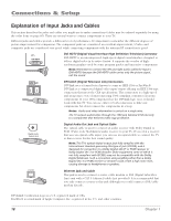
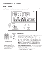
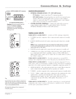
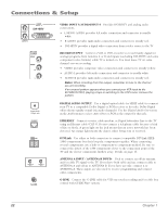
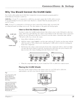
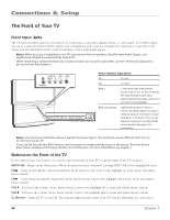
Connections & Setup CENTER CHANNEL INPUT INTERNAL SPEAKER SOURCE TV EXT AMP TV's CENTER CHANNEL INPUTS Caution: Do not connect the A/V receiver's CENTER CHANNEL output to the TV's EXTERNAL SPEAKERS terminals. Damage to TV may occur. CENTER SPEAKER INPUT • INTERNAL SPEAKER SOURCE - TV / EXT AMP Switch - TV Position Sound comes from TV's internal speakers. - EXT AMP Position Internal speakers are used for an external center channel. When an external audio/video receiver's center channel output is connected to the TV's center channel input, center channel audio comes out of the TV's internal speakers. • CENTER CHANNEL TERMINALS Connect the audio/video receiver's center channel output to the TV's center channel input. Switch the INTERNAL SPEAKER SOURCE to EXT AMP position. VIDEO INPUT 1 V L/MONO S-VIDEO R AUDIO INPUT 1 VIDEO INPUT 3 V PR L/MONO PB R Y AUDIO INPUT 3 Tips Inputs 3/4 can be used as either a component video (Y PB PR ) input or a composite video (V) input. The TV auto detects the connection with Y PB PR having highest priority. PIP cannot be displayed from component (Y•Pb•Pr) inputs. VIDEO/AUDIO INPUTS VIDEO INPUT 1/AUDIO INPUT 1 Connect an NTSC (analog) component. • V (VIDEO) provides composite video connection and connector is usually yellow. • L/MONO AUDIO provides left audio connection and connector is usually white. Note: If your component has only one output for audio (mono), connect it to the left (white L/Mono) audio jack on the TV and don't connect the right audio part of the cable. • R AUDIO provides right audio connection and connector is usually red. • S-VIDEO lets you connect an S-Video cable for better video quality picture to a component with S-Video capability, such as a VCR or DVD player. When using S-Video, make sure to connect the two audio cables as well as the S-Video connector. VIDEO INPUT 2/AUDIO INPUT 2 Provides connection to a second NTSC (analog) video component such as a VCR. The jacks are as described for INPUT 1. VIDEO INPUT 3/AUDIO INPUT 3 Connect an optional component (Y PB PR) video source, such as a DVD player or satellite receiver. Note that it is essential to match the color coded connectors between a compatible component and the TV. • AUDIO R/L/MONO The audio jacks provide stereo sound. When connected, audio volume from the main front and rear speakers are variable. • V (VIDEO) provides composite video connection and connector is usually yellow. • Y P P Unlike a single video input, component video maintains the video B R signal as three separate parts through these three jacks. To ensure maximum picture quality, use three video-grade cables for the Y PB PR connections. Accepts 480i, 480p, 1080i signals. Has priority over V connection. VIDEO INPUT 4/AUDIO INPUT 4 Provides connection to a second optional component video source, such as a DVD player or satellite receiver. The jacks are the same as described in INPUT 3. Chapter 1 21
-
 1
1 -
2
-
3
-
4
-
5
-
6
-
7
-
8
-
9
-
10
-
11
-
12
-
13
-
14
-
15
-
16
-
17
-
 18
18 -
 19
19 -
 20
20 -
 21
21 -
 22
22 -
 23
23 -
 24
24 -
 25
25 -
 26
26 -
 27
27 -
 28
28 -
29
-
30
-
31
-
32
-
33
-
34
-
35
-
36
-
37
-
38
-
39
-
40
-
41
-
42
-
43
-
44
-
45
-
46
-
47
-
48
-
49
-
50
-
51
-
52
-
53
-
54
-
55
-
56
-
57
-
58
-
59
-
60
-
61
-
62
-
63
-
64
-
65
-
66
-
67
-
68
-
69
-
70
-
71
-
72
-
73
-
74
-
75
-
76
-
77
-
78
-
79
-
80
-
81
-
82
-
83
-
84
-
85
-
86
-
87
-
88
-
89
-
90
-
91
-
92
-
93
-
94
-
95
-
96
 |
 |
