RCA HD61LPW42 User Guide & Warranty - Page 24
Video Input 5/audio Input 5, Record Output, Digital Audio Output, Ethernet, Dtvlink, Antennainput /
 |
UPC - 034909312742
View all RCA HD61LPW42 manuals
Add to My Manuals
Save this manual to your list of manuals |
Page 24 highlights
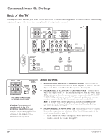
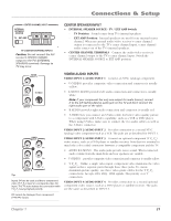
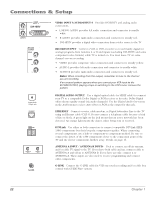
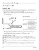
Connections & Setup L/MONO VIDEO INPUT 5 DVI-HDTV R AUDIO INPUT 5 RECORD OUTPUT VIDEO AUDIO R L Digital Audio Output Jack ETHERNET ANTENNA B INPUT ANTENNA A INPUT G-LINK VIDEO INPUT 5/AUDIO INPUT 5 Provides DVI-HDTV and analog audio connections. • L/MONO AUDIO provides left audio connection and connector is usually white. • R AUDIO provides right audio connection and connector is usually red. • DVI-HDTV provides a digital video connection from a video source to the TV. RECORD OUTPUT Connect a VCR or DVD-recorder to record mainly digital (or analog) programs from Antenna A or B and inputs (excluding DVI-HDTV and some component video formats) while TV is turned on. You must leave TV on same channel you are recording. • VIDEO provides composite video connection and connector is usually yellow. • AUDIO L provides left audio connection and connector is usually white. • AUDIO R provides right audio connection and connector is usually red. Notes: When recording from this output, remember to tune to the channel you are recording. If an unusual pattern appears when you connect your VCR input to the RECORD OUTPUT, playing a tape or switching to the VCR's tuner removes the pattern. DIGITAL AUDIO OUTPUT Use a digital optical cable (or SPDIF cable) to connect your TV to a compatible Dolby Digital or PCM receiver or decoder. Dolby Digital offers theatre-quality sound (six audio channels). Use the Digital Audio Out screen in the Audio menu to select Auto Select or PCM as the output for this jack. ETHERNET Connect a router, cable modem, or Digital Subscriber Line to the TV using an Ethernet cable (CAT 5). Do not connect a telephone cable because of risk of fire or shock. A green light on the jack means that an active network has been detected. An orange light means the data is either being sent or received. DTVLink Use either or both connectors to connect compatible DTVLink (IEEE1394) components but don't loop the components together. When connecting several components, use a hub or component-to component method. Be sure to connect the fastest of the 1394 components closer to the connection point of the TV and the slower components furthest away. Details on page 16. ANTENNA A INPUT / ANTENNA B INPUTs Used to connect an off-air antenna and/or cable TV signal to the TV. If you have both cable and air, connect cable to ANTENNA A and off-air to ANTENNA B. If you have air only, connect it to ANTENNA A. These inputs are also used to receive programming and connect older components. G-LINK Connect the G-LINK cable for VCR one touch recording and/or cable box control with GUIDE Plus+ system. 22 Chapter 1
-
 1
1 -
2
-
3
-
4
-
5
-
6
-
7
-
8
-
9
-
10
-
11
-
12
-
13
-
14
-
15
-
16
-
17
-
18
-
 19
19 -
 20
20 -
 21
21 -
 22
22 -
 23
23 -
 24
24 -
 25
25 -
 26
26 -
 27
27 -
 28
28 -
 29
29 -
30
-
31
-
32
-
33
-
34
-
35
-
36
-
37
-
38
-
39
-
40
-
41
-
42
-
43
-
44
-
45
-
46
-
47
-
48
-
49
-
50
-
51
-
52
-
53
-
54
-
55
-
56
-
57
-
58
-
59
-
60
-
61
-
62
-
63
-
64
-
65
-
66
-
67
-
68
-
69
-
70
-
71
-
72
-
73
-
74
-
75
-
76
-
77
-
78
-
79
-
80
-
81
-
82
-
83
-
84
-
85
-
86
-
87
-
88
-
89
-
90
-
91
-
92
-
93
-
94
-
95
-
96
 |
 |
