Sharp AR-MM9 Service Manual
Sharp AR-MM9 - Memory Board - DRAM Manual
 |
UPC - 074000074828
View all Sharp AR-MM9 manuals
Add to My Manuals
Save this manual to your list of manuals |
Sharp AR-MM9 manual content summary:
- Sharp AR-MM9 | Service Manual - Page 1
SERVICE MANUAL CODE: 00ZARFX7//A1E DIGITAL MULTIFUNCTIONAL SYSTEM OPTION FACSIMILE EXPANSION KIT (For U.S.A./Canada) MODEL AR-FX7 EXPANSION MEMORY 8MB: AR-MM9 CONTENTS [1] OUTLINE 1-1 [2] SPECIFICATIONS 1-1 [3] INSTALLATION PROCEDURE 3-1 [4] OPERATION, DISPLAY SECTION 4-1 [5] ADJUSTMENTS 5-1 - Sharp AR-MM9 | Service Manual - Page 2
- Sharp AR-MM9 | Service Manual - Page 3
On-line 8-4 [9] FLASH ROM VERSION UP PROCEDURE 1. Program download method (for Copier, and fax program 9-1 2. Others (Troubleshooting 9-2 [10] TROUBLE CODE LIST 1. Machine trouble codes 10-1 2. Communication result code 10-2 A. Composition of communication report code 10-2 3. List of buzzer - Sharp AR-MM9 | Service Manual - Page 4
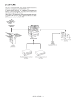
digital machine AR-M237/M277 series. To expand facsimile functions, use of RSPF memory (standard). An expansion memory of one of 8MB can be added. (8MB expansion memory for fax, AR-MM9) Job separator (AR-TR3) Finisher (AR-FN5N) AR-M237/M277 8MB AR-MM9 Expansion memory Facsimile expansion Kit (AR - Sharp AR-MM9 | Service Manual - Page 5
manual memory full Quick online transmission Direct transmission Default setup YES Max. 50 items Transmission cancel or only scanned data transmission YES (Enable/Disable setup by key operator program) YES (100 pages from RSPF, only 1 page from OC) Set by key operator program AR-FX7 SPECIFICATIONS - Sharp AR-MM9 | Service Manual - Page 6
Sharp relay broadcast instructing transmission function Only from the machine having Sharp relay broadcast transmission function NO 10 groups YES YES Only Sharp machine having confidential function F code support machine (8) Scan specification Non-call reception Manual reception setup Setup for - Sharp AR-MM9 | Service Manual - Page 7
's number User tag classification International communication mode setup Transmission method available (5) Registered data read/write YES (Service tool. Dial registration can be made with Backup Backup of registration in power SRAM used, by built-in battery failure 8. AR-FX7 SPECIFICATIONS 2 - 3 - Sharp AR-MM9 | Service Manual - Page 8
reservation) Printout confirmation Memory use status Document data memory backup in power failure 2MB 8MB YES YES YES (% display) YES (Flash memory) 10. Additional Swedish, Italian, Spanish, German, Dutch, Danish, Finish/Norwegian (RX only to TX. not available) AR-FX7 SPECIFICATIONS 2 - 4 - Sharp AR-MM9 | Service Manual - Page 9
remove the cut-out portion from the left rear cabinet using a tool such as nippers. Be careful about the rear cabinet using supplied two golden screws (M3). M3 golden screws Installation manual: Operation manuals: 1 FAX expansion PWB and secure it using six M3 screws with washer. M3 Screws - Sharp AR-MM9 | Service Manual - Page 10
PWB. FCC label 10) Clear the image memory. * If an extended memory (AR-MM9) has been mounted in step 7, be sure to carry out this step. If no extended memory has been mounted, this step is not necessary. [P], [*], [C], and [*] to enter the simulation mode. Use the 10-key pad to enter "66 - Sharp AR-MM9 | Service Manual - Page 11
Use the 10-key pad to enter "1" in the submenu screen shown below and press the START key. The screen shown below is displayed and memory clear operation is executed to restart the main unit. After several minutes, memory clear operation is completed and then the screen shown below is - Sharp AR-MM9 | Service Manual - Page 12
- Sharp AR-MM9 | Service Manual - Page 13
keys Use to select the basic modes memory. The light stays on constantly when a fax is waiting in memory for transmission. 9 [CUSTOM SETTINGS] key Use to customize the machine settings to better suit your needs. When using ALL] key Use to cancel key is also used to cancel an can be used to set - Sharp AR-MM9 | Service Manual - Page 14
key 8 [DIRECT TX MEMORY TX] key 9 [SPECIAL memory that is free and the currently selected reception mode. This key is used to use an auto memory Program, Memory box, manually ADDRESS REVIEW FREQUENT USE ABCD EFGHI JKLMN OPQRST 6 or 12 using a key operator used used as follows: • For storing destinations - Sharp AR-MM9 | Service Manual - Page 15
-key to adjust the FAX image density. 5) Make a copy, and adjust so that the following adjustment specification is satisfied. ∗ When an adjustment is made in this mode, the exposure level for each communication mode greater the density is, and vice versa. Set range 0 - 99 AR-FX7 ADJUSTMENTS 5 - 1 - Sharp AR-MM9 | Service Manual - Page 16
value: 0 to 21 Transmission level: 0.0 to -21dB +2.0 SW set value: dBm 0 to 15 Transmission level: 2.0 to 5.5dB 1dBm step (Binary input) 0.5dBm step (Binary input) AR-FX7 ADJUSTMENTS 5 - 2 - Sharp AR-MM9 | Service Manual - Page 17
memory clear Used to send 300bps signals. (Signal send level: Max.) Used to send 300bps signals. (Signal send level: Set by soft SW) Used to register the dial numbers. Used to perform the dial test. (10 PPS send test) Used When the AR-NC5 is installed, the AR-NC5J Panel software support language - Sharp AR-MM9 | Service Manual - Page 18
countries *1: Display at the current state Panel software support language English, German, French, Spanish, Dutch, Italian ) Adjustment/setting/operation data output/check (display/print) Used to display the FAX send/receive counter (FAX reception is installed. 1 50 AR-FX7 SIMULATION 6 - 2 - Sharp AR-MM9 | Service Manual - Page 19
Fine AE (Half tone) 4 AE (PHOTO OFF) Super Fine AE 5 MANUAL Super Fine MANUAL 0 - 99 50 (PHOTO ON) (Half tone) 6 MANUAL Super Fine MANUAL (PHOTO OFF) Note:Executable only when the FAX is installed. 1 3 the exposure level with the 10-key, and press the [#/P] key. AR-FX7 SIMULATION 6 - 3 - Sharp AR-MM9 | Service Manual - Page 20
AE (Half tone) 4 AE (PHOTO OFF) Ultra Fine AE 5 MANUAL Ultra Fine MANUAL 0 - 99 50 (PHOTO ON) (Half tone) 6 MANUAL Ultra Fine MANUAL (PHOTO OFF) Note: Executable only when the FAX is installed. 1 paper passing) Note: Executable only when the FAX is installed. AR-FX7 SIMULATION 6 - 4 - Sharp AR-MM9 | Service Manual - Page 21
50 43-57 50 Note: Executable only when the FAX is installed. 1 66 66-1 Purpose Setting Function Used to change and check the FAX-related soft SW. (Purpose) Section FAX Operation/procedure 1. Enter the soft monitoring it. Note: Executable only when the FAX is installed. AR-FX7 SIMULATION 6 - 5 - Sharp AR-MM9 | Service Manual - Page 22
Purpose Adjustment Function Used to clear the "NG" is notified to the error address. 5 After completion of check, the memory is returned to the initial state. (CPU is not reset) Interruption cannot be made - 23 7.2 V29 - 24 4.8 V27t - Send level Selection menu None AR-FX7 SIMULATION 6 - 6 - Sharp AR-MM9 | Service Manual - Page 23
BOX names, and confidential password) is printed. The confidential data of My company mode is printed separately. Note: Executable only when the FAX is installed. AR-FX7 SIMULATION 6 - 7 - Sharp AR-MM9 | Service Manual - Page 24
" with the 10-key and press the [START] key. (When "2: NO" is selected, the simulation is canceled.) Used to clear all image data (including confidential reception data) stored in image memory of the FAX section. The management table is also cleared (initialized) at the same time. * lIf there is - Sharp AR-MM9 | Service Manual - Page 25
Executable only when the FAX is installed. 66-14 Purpose Function (Purpose) Section Item Operation check/test Used to perform the dial test. (10 PPS send test) FAX Operation Operation/Procedure 1. Select the item - 0-15 Note: Executable only when the FAX is installed. AR-FX7 SIMULATION 6 - 9 - Sharp AR-MM9 | Service Manual - Page 26
backed up. (When "2: NO" is selected, the simulation is canceled.) * The AR-FX5 data cannot be written into the AR-FX7. If it is executed, data are initialized and deleted. In addition, the AR-FX7 data cannot be used in the AR-FX5. Note: Executable only when the FAX is installed. 66-20 Purpose - Sharp AR-MM9 | Service Manual - Page 27
the FAX is installed. 66-30 Purpose Function (Purpose) Section Item Operation/procedure Operation test/check Used to set the TEL/LIU. FAX Operation When the relay state of the polarity reverse relay, , "NG" is displayed. Note: Executable only when the FAX is installed. AR-FX7 SIMULATION 6 - 11 - Sharp AR-MM9 | Service Manual - Page 28
measuring How to check the time Measuring unit Communication : Memory send means : Normal Character Picture quality : Lighter reception before reception of image data until reception of RCP frame Used to make communication not in a simulation process but in the AR-FX7 SIMULATION 6 - 12 - Sharp AR-MM9 | Service Manual - Page 29
None SG3 G3 Reception G3/SG3 SG3 G3 V34 send speed Manual send V34 One-touch/ Reduction, etc. None V29 no modulation communication trouble occurs. When an error occurs in the SG3 communication. When an error occurs in the SG3 communication in FAX service, etc error AR-FX7 SOFT SWITCH 7 - 1 - Sharp AR-MM9 | Service Manual - Page 30
. 12 00 01 345678 1: English 1: ON 1: ON 0: OFF 0: OFF 1: Yes 0: No 1: Host-Tel-No. 0: Service-No. 1: DM Bit No. 75K 50K 25K 20K 10K 5K Free except for the above. 567 001 010 011 100 101 110 0: AR Binary input Bit No. Setting range 5678 0 to 15 times 0 fixed Default value Remarks - Sharp AR-MM9 | Service Manual - Page 31
Manual reception 0: Debug mode OFF 0: 256byte 0: Output 5678 0 to 750ms 0: Automatic reception 2 Inhibited to use 3 Size specification Bit No. 34 Centimeter size 0 0 Inch size 10 S4 W 6 Follows the machine information. Follows the 01 11 machine information. 5 Inhibited to use 6 Memory - Sharp AR-MM9 | Service Manual - Page 32
Department management 1: Allowed 0: Inhibited 2 Inhibited to use 3 Sender's telephone number 1: No 0: Yes registration 4 Yes/No of manual send 1: Displayed 0: Not displayed selection menu display the value is 0 outside the setting 1 range, the initial 1 value is set. AR-FX7 SOFT SWITCH 7 - 4 - Sharp AR-MM9 | Service Manual - Page 33
) S 4 ECM JBIG mode (except for 1: Yes W SG3) 17 5 Inhibited to use 0: No 6 MH fixed (SG3) 1: Yes 0: None (depending on the remote machine) 6 times 1 0 No 0 Yes 1 Yes 1 0 No 0 Yes 1 Yes 1 0 0 2 times 1 0 0 0 0 0 1 0 750ms 0 1 0 0 0 0 AR-FX7 SOFT SWITCH 7 - 5 - Sharp AR-MM9 | Service Manual - Page 34
use 2 3 4 5 SIM DTMF sound speaker 1: Yes 0: No S selection window W 6 Flash send wait time Bit No. 67 20 0sec 00 0.5sec 01 7 1sec 10 2sec 11 8 Receivable memory 0 Fixed to NONE. 0 Fixed to NONE. No 0 0 0 60ms 0 0 1 0 0 0 0 0 1 100ms 0 1 AR-FX7 SOFT SWITCH 7 - 6 - Sharp AR-MM9 | Service Manual - Page 35
input Bit No. Setting range 5678 30 to 75sec by increment of 5sec 1 Inhibited to use 2 3 S 4 Time specification print Binary W 30 5 (o'clock) on the input Bit No. 6 communication record the value is 0 outside the setting 0 range, the initial 0 value is set. 0 AR-FX7 SOFT SWITCH 7 - 7 - Sharp AR-MM9 | Service Manual - Page 36
. Items SW selection and functions 1 Inhibited to use 2 3 Time specification print Binary S 4 (minute) on the input 1: Yes 0: No to the report table of memory confidential send 8 Total communication time 1: Yes 0: -4 - 5 must be 1 set to output. No 0 Yes 1 AR-FX7 SOFT SWITCH 7 - 8 - Sharp AR-MM9 | Service Manual - Page 37
use W6 36 7 Waiting time for lift-up Bit No. 78 30sec 00 15sec 01 8 60sec 10 120sec 11 1 Thin paper setup 1: Allowed 0: Inhibited 2 Specification of 1m scan 1: Specification 0 Inhibited 0 Normal operation 0 Yes 1 Yes 1 Yes 1 Yes 1 1 Round down 0 AR-FX7 SOFT SWITCH 7 - 9 - Sharp AR-MM9 | Service Manual - Page 38
Specification of data output 1: Not output 0: Output in case of a communication Output 0 error in reception 3 Memory data duplex print 1: Yes 40 7 Specification of print 1: Print order (214365 214365...) 1 8 Specification of rotating 1: No Yes 1 2 Inhibited to use 0 S3 0 W4 0 41 - Sharp AR-MM9 | Service Manual - Page 39
tone 7 Bit No. 550Hz 1000Hz 1700Hz 67 00 01 10 0 1000Hz 1 8 V.34 mode function in manual communication 1: ON 0: OFF ON 1 1 V.34 mode function 1: ON 0: OFF ON 1 2 Super G3 input Bit No. Setting range 345678 Pattern No.: 1 to 35 1 0 21 1 7 0 8 1 AR-FX7 SOFT SWITCH 7 - 11 Remarks - Sharp AR-MM9 | Service Manual - Page 40
1: 350ms (Lower limit) 0: 750ms 0: 250ms 5 Busy tone detection time 1: 150ms 0: Follows SW51-4. (Lower limit 2) 6 Inhibited to use 7 8 SDT signal detection 1: Yes 0: No Default value 1 Middle 0 0 1 0 21 1 0 1 1 Middle 0 0 1 0 21 1 0 1 1 Middle 0 0 1 0 21 1 0 1 1 Middle 0 0 1 0 21 - Sharp AR-MM9 | Service Manual - Page 41
to use 7 8 1 Inhibited to use 2 3 S4 W 53 5 6 7 8 1 Inhibited to use 2 3 S4 W 54 5 6 7 8 1 Inhibited to use 2 3 S4 W 55 5 6 7 8 1 Inhibited to use 2 0 0 0 1 1 0 0 1 0 1 0 0 0 0 0 1 0 0 0 0 0 0 0 0 0 0 0 0 0 0 0 0 1 0 0 0 fixed 0 0 0 0 0 fixed 0 0 0 AR-FX7 SOFT SWITCH 7 - 13 - Sharp AR-MM9 | Service Manual - Page 42
use 60 4 Reception gain adjustment 5 6 7 8 1 Inhibited to use 2 3 S W 4 61 5 6 7 8 1 Inhibited to use 2 3 S4 W 62 5 6 7 8 1 Inhibited to use 48dB 1 0 0 1 0.0dBm 1 0 0 1 0 0 1 1 1 1 0 0 0 0 0 0 0 0 0 1 1 1 0 0 0 1 0 Remarks AR-FX7 SOFT SWITCH 7 - 14 - Sharp AR-MM9 | Service Manual - Page 43
Inside document position setup S 4 Error message display in 1: Allowed W manual send (For avoiding 66 violation of Patents) 0: Outside document 0: Inhibited Outside document 0 Inhibited 0 5 Inhibited to use 0 6 Polarity reversion Binary 0 7 settlement time 8 input Bit No. Setting - Sharp AR-MM9 | Service Manual - Page 44
Items SW selection and functions Default value Remarks 1 Reception size specification Bit No. 12 (Reception capacity) By the equipped 0 0 to use 0 2 0 3 S 4 Telephone line menu W 71 5 Inhibited to use 6 1: Inhibited 0: Allowed Allowed 0 0 Allowed fixed 0 0 7 1 8 0 AR-FX7 SOFT - Sharp AR-MM9 | Service Manual - Page 45
11 Default value 0 3 times 0 0 1 4 0 0 0 reception & EYE-Q check 0 Process is not continued. (Judged as an 0 error.) Error 0 1 60 lines 0 0 6sec 0 3.4sec 0 0 2-flag 0 0 1 400ms 0 0 0 1.0sec 1 0 0.2sec 0 Remarks AR-FX7 SOFT SWITCH 7 - 17 - Sharp AR-MM9 | Service Manual - Page 46
use 2 3 S4 W 76 5 6 7 8 1 Inhibited to use 2 3 S4 W 77 5 6 7 8 1 Inhibited to use 2 3 S W 4 78 5 6 7 8 1 Inhibited to use 2 3 S4 W 79 5 6 7 8 1 Inhibited to use 1 0 0 0 1 1 0 1 0 0 0 0 1 0 0 0 0 1 0 1 1 0 0 0 0 1 0 1 1 0 0 0 0 1 0 1 1 0 0 0 Remarks AR-FX7 SOFT SWITCH 7 - 18 - Sharp AR-MM9 | Service Manual - Page 47
2 CI signal OFF time in V.8 1: 2sec 0: 1sec mode 3 Inhibited to use 4 CI receive number to shift to Bit No. 45 S non-V.34 communication Does 0 outside the setting range, the initial value is set. 0 10sec 155ms 0 1 0 PWB for Australia 0 only can be changed. 0 AR-FX7 SOFT SWITCH 7 - 19 - Sharp AR-MM9 | Service Manual - Page 48
use 1 Inhibited to use 2 3 S4 W 88 5 6 7 8 1 Inhibited to use 2 3 S W 4 89 5 6 7 8 1 Inhibited to use 2 3 S4 W 90 5 6 7 8 1 Inhibited to use 2 3 S4 W 91 5 6 7 8 1 Inhibited to use 0 0 0 0 0 1 0 1 1 0 0 0 1 0 0 0 0 0 0 0 Remarks AR-FX7 SOFT SWITCH 7 - 20 - Sharp AR-MM9 | Service Manual - Page 49
use 2 3 S W 4 96 5 6 7 8 1 Inhibited to use 2 3 S4 W 97 5 6 7 8 1 Inhibited to use 2 3 S4 W 98 5 6 7 8 1 Inhibited to use 2 3 S4 W 99 5 6 7 8 1 Inhibited to use 0 0 0 0 0 0 0 0 0 0 0 0 0 0 0 0 0 0 0 0 0 0 0 0 1 0 0 Remarks AR-FX7 SOFT SWITCH 7 - 21 - Sharp AR-MM9 | Service Manual - Page 50
S4 W 105 5 6 7 8 1 Inhibited to use 2 3 S4 W 106 5 6 7 8 1 Inhibited to use 2 3 S4 W 107 5 6 7 8 SW selection and functions Default value 0 0 1 1 1 1 0 0 0 0 1 0 1 1 0 1 0 1 1 0 1 1 0 1 0 0 0 0 0 0 0 0 0 0 0 0 0 0 0 0 1 0 1 0 1 1 0 1 0 0 1 0 0 0 0 0 Remarks AR-FX7 SOFT SWITCH 7 - 22 - Sharp AR-MM9 | Service Manual - Page 51
SW Data No. No. Items SW selection and functions 1 Inhibited to use 2 3 S4 W 108 5 6 7 8 1 Print lead edge 0 to ±56 lines in the interval of 8 lines 0: + 678 0 to ±56 lines in the interval of 8 lines AR-FX7 SOFT SWITCH 7 - 23 Default value 0 0 0 0 0 1 0 1 + 0 0 48 dots 1 1 - Sharp AR-MM9 | Service Manual - Page 52
not a coordinate 0 value, its unit differs from that of the other set values. The value cannot be increased 0 over the coordinates specified in scanning. 0 0 0 0 0 0 +0 dots 0 0 AR-FX7 SOFT SWITCH 7 - 24 - Sharp AR-MM9 | Service Manual - Page 53
differs from that of the other set values. The value cannot be increased 0 over the coordinates specified in scanning. 0 0 0 0 0 0 +0 dots 0 0 + 0 0 0 0 0% 0 0 0 0 + 0 0 0 0 0% 0 0 0 0 + 0 0 0 0 0% 0 0 0 0 + 0 0 0 0 0% 0 0 0 0 AR-FX7 SOFT SWITCH 7 - 25 - Sharp AR-MM9 | Service Manual - Page 54
3 S4 W 131 5 6 7 8 1 Inhibited to use 2 3 S4 W 132 5 6 7 8 Default value + 0 0 0 0 0% 0 0 0 0 + 0 0 0 0 0% 0 0 0 0 0 0 0 1 1 0 1 0 0 0 1 0 0 0 1 0 0 0 1 0 1 0 1 0 0 0 0 1 0 0 0 0 0 0 1 0 0 0 0 0 Remarks AR-FX7 SOFT SWITCH 7 - 26 - Sharp AR-MM9 | Service Manual - Page 55
AR) SW4 No.1-4 Inhibited to use. SW4 No.5-No.8 RingBackTone pre-send times Used ) SW5 No. 3 Flash memory check measuring range Operation check usually can be manual reception. When set to 0, auto reception. Default: 0 (Auto reception) SW6 No. 2 Inhibited to use. SW6 No.3, No.4 Size specification Used - Sharp AR-MM9 | Service Manual - Page 56
in manual reception Used to set whether reception from manual reception is rejected or not when reception function by specifying the number is ON. Default: 1 (Reject specified number reception) SW10 No. 1 F-code relay broadcast function Used to set whether F code relay broadcast instruction from - Sharp AR-MM9 | Service Manual - Page 57
SW11 No. 4 Yes/No of manual send selection menu display Used to set whether the manual transmission selection screen is displayed or not interval in communication error Used to set recall interval after disconnection of communication due to a communication error in memory transmission. The set range - Sharp AR-MM9 | Service Manual - Page 58
use. SW17 No. 6 MH fixed (SG3) Used Used Used Used use. SW19 No.1-No.4 Minimum pause time (10PPS) setup Used memory capacity Used to set the remaining memory capacity for acceptance of call. When set to 1, ringing is made until the remaining memory Used use. SW22 No.1, No.2 Waiting time for dial start Used - Sharp AR-MM9 | Service Manual - Page 59
printed. When set to 0, the table is not printed though the data reaches 50 items. Default: 0 (No print) SW29 No. 2 Time specification of communication record table Used to set whether time is enabled or not in the output function of communication record table at the specified time. Linked with the - Sharp AR-MM9 | Service Manual - Page 60
No.3-No.8 Time specification print (min) on the communication report table Used to set "min" attach images to the report table of memory confidential send Used to set whether images are attached to the report table of memory confidential send Default: 0 (NO) print enable) AR-FX7 SOFT SWITCH 7 - 32 - Sharp AR-MM9 | Service Manual - Page 61
Thin paper setup Used to set whether the thin paper use is allowed or not. Default: 0 (Inhibited) SW37 No. 2 Specification of 1m scan when there is no line send setting Used to set "Reception specification of 1m" when : 0 (Output is made after reception of every page) AR-FX7 SOFT SWITCH 7 - 33 - Sharp AR-MM9 | Service Manual - Page 62
SW39 No. 2 Specification of data output in case of a communication error in reception Used to set whether the image on the page where a communication error occurred during image reception is printed or not. "1": Setup not to print "0": Setup to print Default: 0 (Print) SW39 No. 3 Memory over during - Sharp AR-MM9 | Service Manual - Page 63
manual communication. When set to 1, V.34 mode function is enabled. When set to 0, V.34 mode function is disabled. Default: 1 (V.34 mode function is enabled.) SW43 No. 1 V.34 mode function Used to set whether V.34 mode is used SW51-4) SW51 No. 6, No. 7 Inhibited to use. AR-FX7 SOFT SWITCH 7 - 35 - Sharp AR-MM9 | Service Manual - Page 64
time Used to use. SW58 No.3-No.8 External connection sound volume Used send level Max. Used to set Signal send level Used to set and low level) Used to set the Used Used Used manual transmission. Default: 0 (Inhibited) SW66 No. 5 Inhibited to use. SW66 No.6-No.8 Polarity reversion settlement time Used - Sharp AR-MM9 | Service Manual - Page 65
Used to set YES/NO of measurement. Used Used . 7 ECM Used to set whether using that tray. Default: Tray 1 - tray 4 are used. (1) bit 1 : Tray 1 bit 2 : Tray 2 bit 3 : Tray 3 bit 4 : Tray 4 SW68 No.5-No.8 The tray specification of Duplex print (Tray 1 - 4) Used not use specification length Used Used Used - Sharp AR-MM9 | Service Manual - Page 66
to set CED signal send time. Default: 0 0 (3 sec) SW75 No.5, No.6 Waiting time for ANSam send start Used to set the waiting time for ANSam send start. Default: 0 0 (2.25 sec) SW75 No.7, No.8 ANSam signal send time Used to set ANSam signal send time. Default: 0 1 (4 sec) AR-FX7 SOFT SWITCH 7 - 38 - Sharp AR-MM9 | Service Manual - Page 67
: 10sec 1 0 : 15sec 1 1 : 20sec Default: 0 1 (10 sec) SW86 No.6-No.8 CI signal ON detection enable time Used to set the time to judge that CI signal is ON. The CI signal of less than this setup time is not regarded as ON 112 dots in the interval of 16 dots Default: 48 dots AR-FX7 SOFT SWITCH 7 - 39 - Sharp AR-MM9 | Service Manual - Page 68
(main scan) Used to adjust the sub scan) Used to adjust image loss Used to set the (OC) Used to set edge image loss Used to set the edge image loss Used to set the OC (main scan) Used to adjust the OC (sub scan) Used to adjust the image loss Used to set the ) Used to edge image loss Used to set the - Sharp AR-MM9 | Service Manual - Page 69
SIM 48-8 is reflected. 0 to ±12.7% by increment of 0.1% Default: 0% SW128 No.1-No.8 Inhibited to use. SW129 No.1-No.8 Inhibited to use. SW130 No.1-No.8 Inhibited to use. SW131 No.1-No.8 Inhibited to use. SW132 No.1-No.8 Inhibited to use. SW133 No.1-No.8 Inhibited to use. AR-FX7 SOFT SWITCH 7 - 41 - Sharp AR-MM9 | Service Manual - Page 70
- Sharp AR-MM9 | Service Manual - Page 71
-registering∗ Registering / Un-registering∗ Remarks Half tone cannot be selected for standard resolution. Only when an extension phone is connected This method can only be used if the other machine is also a Sharp machine (excluding certain models). AR-FX7 KEY OPERATOR PROGRAM 8 - 1 - Sharp AR-MM9 | Service Manual - Page 72
code list F-code memory box list Junk FAX number list Used to print the FAX key operator program. Used to print communication time and communication pages in each department. Used to print the at a specified time, change the setting in the key operator programs. AR-FX7 KEY OPERATOR PROGRAM 8 - 2 - Sharp AR-MM9 | Service Manual - Page 73
original size Using the RSPF 880 mm]. Using the document glass 11" amount of memory is limited memory fills up before the entire original can be scanned, use ↑ 1) SHARP PLANNING DIV. use manual transmission or Quick On-Line transmission). If desired, you can use use the same size of paper - Sharp AR-MM9 | Service Manual - Page 74
however, when both the sender and the receiver use the same size of paper, the printed fax used for memory transmission and there are no previously stored jobs waiting or in progress (and the line is not being used is transmitted using the following methods, the job will be stored in memory (Quick - Sharp AR-MM9 | Service Manual - Page 75
1) Make sure copier is off, and connect it to PC with download cable beforehand. 2) Start up the maintenance program on PC. Select model name "AR-M236/M276/M237/M277 Series" from the model selection dialogue box. 6) When downloading copier program, expand "Special(Copier)", and double-click on "All - Sharp AR-MM9 | Service Manual - Page 76
the job. [TROUBLESHOOTING] To change destination not correct. [TROUBLESHOOTING] Confirm the TROUBLESHOOTING TROUBLESHOOTING procedure. [TROUBLESHOOTING] Confirm the TROUBLESHOOTING TROUBLESHOOTING [TROUBLESHOOTING] using other application. The error occurred except the above errors. [TROUBLESHOOTING - Sharp AR-MM9 | Service Manual - Page 77
FAX control PWB and MCU PWB. Check the grounding of the copier. Check FAX control PWB ROM. Trouble code Main Sub code code F6 82 Content Details Cause Check and remedy 84 Content Details Cause Check setup (Sim 22-6) and FAX country code (Soft SW table). AR-FX7 TROUBLE CODE LIST 10 - 1 - Sharp AR-MM9 | Service Manual - Page 78
result code: Codes used by serviceman. Top Power OFF Reception memory over Reception length instruction, 2) When a receiving station number that is not registered is instructed in reception of the relay instruction, 3) When F code relay instruction AR-FX7 TROUBLE CODE LIST 10 - 2 - Sharp AR-MM9 | Service Manual - Page 79
Various internal operation abnormality Trouble content Expanded memory reinsertion PWB solder trouble, PWB parts trouble Download retry Download retry IC13, 14: PWB solder trouble, PWB parts trouble IC41: PWB solder trouble, PWB parts trouble IC41: PWB solder trouble, PWB parts trouble MCU - Sharp AR-MM9 | Service Manual - Page 80
- Sharp AR-MM9 | Service Manual - Page 81
VERTICAL SCANNING 1/2X MN 86065 I/F CPU I/F FAX GA I/F LINE EX TEL Speaker Handset (Japan only) LIU PWB SILICON DAA PSUED RINGER (JAPAN ONLY) ADD-ON MEMORY (AR-MM9) 8MB CPU (SH7709A) MEM ORY back up BACK UP MEBMACOKRYUP SMREAMMORY 2MSbRiAt M 2Mbit x 2 MODEM MN195006-E PAGE - Sharp AR-MM9 | Service Manual - Page 82
/PTG(7) PTG(4) IRQ3/IRL3/PTH(3) ADTRG/PTH(5) CASLH/CASU/PTJ(3) RAS2L/PTJ(1) WE3/DQMUL/ICIOWR/PTK(7) WE2/DQMUL/ICIORD/PTK(6) R 312 10K R 313 10K GN D 8 7 6 5 AR-FX7 ELECTRICAL SECTION 11 - 2 - Sharp AR-MM9 | Service Manual - Page 83
VR SEL [3]VR SEL [2]VR SEL [1]- LI UID HS 1 RHS EXHS- 8 7 6 5 100 R 408 +3.3V BR 39 MNR04 10K C 325 B1000/5 0 GN D HS 2- 4 3 2 1 CASL- R AS3 L- A CK E 4 3 2 1 AR-FX7 ELECTRICAL SECTION 11 - 3 - Sharp AR-MM9 | Service Manual - Page 84
) GN D GN D A TP392 IC 11D R253 0 9 8 TP389 TC74LCX05FT R 254 TP391 0 11 IC 11E 10 TP388 TC74LCX05FT R 255 TP390 0 13 IC 11F 12 TP387 TC74LCX05FT GN D 4 3 AR-FX7 ELECTRICAL SECTION 11 - 4 SW2 SW2 SW2 10K R600 - Sharp AR-MM9 | Service Manual - Page 85
GND NC C B DMM2-SD72A-1131 6 5 4 GN D Normally operation Download execution Download creation (OP→STD) (STD→OP) SW2-1 SRAM clear SW2-2 SW2-3 A : With jumper : No jumper 2 1 AR-FX7 ELECTRICAL SECTION 11 - 5 - Sharp AR-MM9 | Service Manual - Page 86
+3.3V D2 5 1SS355(NM) D2 4 1SS355(NM) TP1233 C 417 F1u/10(1608)(NM) ZD 3 U D Z 2.0B TP1234 R 290 1K R 288 36 0 C B Q11 KTC3875 E R 289 560 GN D A AR-FX7 ELECTRICAL SECTION 11 - 6 - Sharp AR-MM9 | Service Manual - Page 87
16A KIA393F (NM) C5 8 C(NM) GN D GN D 2 TP1009 R8 0 0 TP1136 65+ 7 IC 16B KIA393F (NM) TP378 GN D GN D L_BT- A C_BT C_BT Q2 DTC363EKA T146 B C E GN D B AR-FX7 ELECTRICAL SECTION 11 - 7 - Sharp AR-MM9 | Service Manual - Page 88
1A3 1A4 2A1 2A2 2A3 2A4 2 4 6 8 11 13 15 17 +3.3V C8 5 F 0 .1u/16 20 VCC 10 GND 1G 2G 1 19 GN D TC74LCX244FT GN GN D 8 7 6 5 AR-FX7 ELECTRICAL SECTION 11 - 8 - Sharp AR-MM9 | Service Manual - Page 89
GN D +3.3V D8 1SS355 TP1124 R8 8 R 263 0 0 C8 3 F 0 .1u/16 IC25 3 IN 1 GND LM1117MPX-1.8 OUT1 2 OUT2 4 C8 4 F 0 .1u/16 TP410 C8 2 A33u/10 +1.8V GN D 4 3 2 AR-FX7 ELECTRICAL SECTION 11 - 9 A 1 - Sharp AR-MM9 | Service Manual - Page 90
B CS 0CS 4CS 6- BSRD/ WR- RDWE0 WE1 R1006 R1007 DRAK[ 0] DRAK[ 1] WA IT- GN D 3.3V GA1 C115 F 0 .1u/16 GN D C DRE Q[0]DRE Q[1]- AR-FX7 ELECTRICAL SECTION 11 - 10 VDD- 77 VDD- 78 A[1] A[2] A[3] A[4] A[5] A[6] A[7] A[8] A[9] A[10] A[11] A[12] A[13] A[14] A[15] A[16] GN D -95 GN D -96 A[20] A[21 - Sharp AR-MM9 | Service Manual - Page 91
C 112 F 0 .1u/16 3.3V GA1 C 113 F 0.1u/16 3.3V GA1 C 114 F 0 .1u/16 R94 R(NM) 3.3VGA1 GN D R95 R(NM) GN D GN D GN D R9 6 0 R9 7 0 GN D D 1 E AR-FX7 ELECTRICAL SECTION 11 - 11 - Sharp AR-MM9 | Service Manual - Page 92
70 TP309 71 TP319 72 TP311 117 116 74 73 120 R122 2K TP347 GN D VCOI 119 TP346 R123 10 C139 B2200/5 0 GN D MN86065 GN D A 4 3 AR-FX7 ELECTRICAL SECTION 11 - 12 - Sharp AR-MM9 | Service Manual - Page 93
TP367 VCC VCC 11 33 +3.3V C 142 VSS VSS 12 34 C 143 A33u/10 F0.1u/16 C144 F 0.1u/16 IS61LV 641 6-12T GN D 6/10 D C B A 2 1 AR-FX7 ELECTRICAL SECTION 11 - 13 - Sharp AR-MM9 | Service Manual - Page 94
GPIO4 GPIO5 76 77 79 81 82 83 R 320 47K R321 47K GN D GN D GN D R 566 14 IC89D 14 IC 89E 33 8 9 10 7 7 TC74LCX04FT TC74L A 8 7 6 5 AR-FX7 ELECTRICAL SECTION 11 - 14 - Sharp AR-MM9 | Service Manual - Page 95
GN D GN D TP147 IC24F 14 13 12 7 TC74LCX04FT GN D TP148 R 620 0 R 622 0 MDM3.3V R 621 R( NM) Vhnd GN D +5V GN D FB 24 MEM2012(NM) GN D A 4 3 2 1 AR-FX7 ELECTRICAL SECTION 11 - 15 - Sharp AR-MM9 | Service Manual - Page 96
33 +3.3V C 205 B0.1u/25(1608) C203 F 0 .1u/16 GN D VSS VSS 12 34 C 204 A33u/10 GN D F 0 .1u/16 IS61LV 641 6-12T GN D A B C AR-FX7 ELECTRICAL SECTION 11 - 16 - Sharp AR-MM9 | Service Manual - Page 97
/16 GN D C SD RAM_CSSDRAM_CLK SDRAM_CKE SDRAM_RASSDRAM_CASSDRA M_WRSDRAM_DQM0 SDRAM_DQM1 SDRAM_BA0 SDRAM_BA1 S DRAM_A0 S DRAM_A1 S DRAM_A2 S DRAM_A3 S DRAM_A4 3.3V GA2 C 196 B0.1u/25(1608) GN D 1 SDRAM_A[0:12] D E AR-FX7 ELECTRICAL SECTION 11 - 17 - Sharp AR-MM9 | Service Manual - Page 98
GND +3.3V C 307 F0.1u/16 12 D 11 CLK 13 CL PR 10 7 GND VCC 14 Q9 GND TP1245 Q8 TP1246 IC 86B T C 7 4LCX74FT GND A 5 4 3 AR-FX7 ELECTRICAL SECTION 11 - 18 - Sharp AR-MM9 | Service Manual - Page 99
QF QG QH VCC 3 4 5 6 10 11 12 13 14 GND 7 T C 7 4 V H C 1 64FT TP1111 TP1110 TP1109 TP1108 TP1107 TP1106 TP1105 C D 2REQC1 +3.3V C 240 F0.1u/16 GND B A 3 2 1 AR-FX7 ELECTRICAL SECTION 11 - 19 - Sharp AR-MM9 | Service Manual - Page 100
D 14 IC 92B 4 3 7 TC74VHC04FT E E GN D Q18 DTC114EKA T146 C B 14 IC92C 6 5 7 TC74VHC04FT C 411 C 412 CI D2C413 GN D B1000/50 B1000/50 B1000/50 GN D GN D GN D 4 3 AR-FX7 ELECTRICAL SECTION 11 - 20 - Sharp AR-MM9 | Service Manual - Page 101
+5VS +24 V ARXD RGDT nAFERESABITCLK AOUT Not use CID SON HS2LIUI D +5V AG Not use AG DG MCLOCK EXHSCION ATXD ASPCLKLIUID2 MRON Not use Not use Not use DG DG +3.3V +5VS +24 V ARXD 7K GN D C235 A47u/16 C 236 A47u/16 GN D GN D TX25-30P-6ST-H1 GN D GN D A 2 1 AR-FX7 ELECTRICAL SECTION 11 - 21 - Sharp AR-MM9 | Service Manual - Page 102
-RD315 L9 SBT-0260 L10 SBT-0260 A S4A 1 3 2 (NM) OUAZ-SH-105D R205 (U) 91 1/4W (E) 0 1/4W 6 4 8 S3A RSB-5 11 13 9 S3B RSB-5 JP5 (NM) 0 1/4W B AR-FX7 ELECTRICAL SECTION 11 - 22 C25 0.47u 250V C - Sharp AR-MM9 | Service Manual - Page 103
(1608) C72 B1000p/50V (1005) C73 A0.33u/50V E (U) for North America, (E) for Europe. R without W number specified is 1/16W. AG 1/4W or more without size specification are DIP. D E AR-FX7 ELECTRICAL SECTION 11 - 23 - Sharp AR-MM9 | Service Manual - Page 104
AR-FX7 ELECTRICAL SECTION 11 - 24 LIU PWB 4 3 2 A B CN1 150VON HS1 ECON MRON LIUID2 ASPCLKATXD CION EXHKDMCLOCK DG AG FNETD AG +5V LIUID HS2 SON CID - Sharp AR-MM9 | Service Manual - Page 105
q PARTS GUIDE CODE :00ZARFX7//P1E DIGITAL LASERCOPIER/ PRINTER OPTION FAX EXPANSION KIT MODEL AR-FX7 CONTENTS 1 Packing material & safety and performance of the set. SHARP CORPORATION This document has been published to be used for after sales service only. The contents are subject to - Sharp AR-MM9 | Service Manual - Page 106
safety maintenance and operation, it must be replaced with the parts specific to the product specification. F Other than this Parts Guide, please refer to documents Service Manual(including Circuit Diagram)of this model. F Please use the 13 digit code described in the right hand corner of front - Sharp AR-MM9 | Service Manual - Page 107
I Index PARTS CODE [C] CPWBN0148QS31 CPWBX0140QS31 [G] GCOVH0024QSEZ [L] LSUPP0001QSZZ [Q] QCNW-0002QSZZ QCNW-7197XCZZ QCNW-7252XCZZ QCNW-7253XCZZ QCNW-7254XCZZ [R] RADPA0001QSZZ RADPA0002QSZZ [S] SPAKA0329QSZZ SPAKA0330QSZZ SPAKA399ACCZZ SPAKP2374ACZZ SSAKA0006UCZZ SSAKA0019SCZZ SSAKA2345QCZZ - Sharp AR-MM9 | Service Manual - Page 108
free solder. The "LF" marks indicated on the PWB's and the Service Manual mean "Lead-Free" solder. The alphabet following the LF mark shows 40°C higher than that of conventional lead solder thread, the use of the exclusive-use soldering iron is recommendable. (2) NOTE FOR SOLDERING WORK Since the - Sharp AR-MM9 | Service Manual - Page 109
recommended by the manufacturer. Dispose of used batteries according to manufacturer's instructions. (Finnish) VAROITUS Paristo voi räjäht "BATTERY DISPOSAL" THIS PRODUCT CONTAINS A LITHIUM PRIMARY (MANGANESS DIOXIDE) MEMORY BACK-UP BATTERY THAT MUST BE DISPOSED OF PROPERLY. REMOVE THE BATTERY - Sharp AR-MM9 | Service Manual - Page 110
, Inc. IBM, PC/ AT, and PowerPC are trademarks of International Business Machines Corporation. Pentium is a registered trademark of Intel Corporation. and copyrights are the property of their respective owners. SHARP CORPORATION Digital Document System Group Products Quality Assurance Department
-
 1
1 -
 2
2 -
 3
3 -
 4
4 -
 5
5 -
 6
6 -
 7
7 -
8
-
9
-
10
-
11
-
12
-
13
-
14
-
15
-
16
-
17
-
18
-
19
-
20
-
21
-
22
-
23
-
24
-
25
-
26
-
27
-
28
-
29
-
30
-
31
-
32
-
33
-
34
-
35
-
36
-
37
-
38
-
39
-
40
-
41
-
42
-
43
-
44
-
45
-
46
-
47
-
48
-
49
-
50
-
51
-
52
-
53
-
54
-
55
-
56
-
57
-
58
-
59
-
60
-
61
-
62
-
63
-
64
-
65
-
66
-
67
-
68
-
69
-
70
-
71
-
72
-
73
-
74
-
75
-
76
-
77
-
78
-
79
-
80
-
81
-
82
-
83
-
84
-
85
-
86
-
87
-
88
-
89
-
90
-
91
-
92
-
93
-
94
-
95
-
96
-
97
-
98
-
99
-
100
-
101
-
102
-
103
-
104
-
105
-
106
-
107
-
108
-
109
-
110
 |
 |
Parts marked with “
” are important for maintaining the safety of the set. Be sure to replace these parts with
specified ones for maintaining the safety and performance of the set.
SHARP CORPORATION
This document has been published to be used
for after sales service only.
The contents are subject to change without notice.
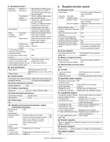
SERVICE MANUAL
CONTENTS
CODE: 00ZARFX7//A1E
DIGITAL MULTIFUNCTIONAL
SYSTEM OPTION
FACSIMILE EXPANSION KIT
(For U.S.A./Canada)
MODEL
AR-FX7
EXPANSION MEMORY
8MB: AR-MM9
[1]
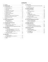
OUTLINE . . . . . . . . . . . . . . . . . . . . . . . . . . . . . . . . . . . . . . . . . . . . 1-1
[2]
SPECIFICATIONS . . . . . . . . . . . . . . . . . . . . . . . . . . . . . . . . . . . . . 1-1
[3]
INSTALLATION PROCEDURE . . . . . . . . . . . . . . . . . . . . . . . . . . . 3-1
[4]
OPERATION, DISPLAY SECTION . . . . . . . . . . . . . . . . . . . . . . . . 4-1
[5]
ADJUSTMENTS . . . . . . . . . . . . . . . . . . . . . . . . . . . . . . . . . . . . . . . 5-1
[6]
SIMULATION . . . . . . . . . . . . . . . . . . . . . . . . . . . . . . . . . . . . . . . . . 6-1
[7]
SOFT SWITCH DESCRIPTIONS . . . . . . . . . . . . . . . . . . . . . . . . . . 7-1
[8]
MACHINE OPERATION . . . . . . . . . . . . . . . . . . . . . . . . . . . . . . . . . 8-1
[9]
FLASH ROM VERSION UP PROCEDURE . . . . . . . . . . . . . . . . . . 9-1
[10]
TROUBLE CODE LIST. . . . . . . . . . . . . . . . . . . . . . . . . . . . . . . . . 10-1
[11]
ELECTRICAL SECTION. . . . . . . . . . . . . . . . . . . . . . . . . . . . . . . . 11-1