Sharp AR-MM9 Service Manual - Page 9
Installation Procedure
 |
UPC - 074000074828
View all Sharp AR-MM9 manuals
Add to My Manuals
Save this manual to your list of manuals |
Page 9 highlights
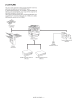
[3] INSTALLATION PROCEDURE 1. Install of expansion kit A. Parts included 2) Work the left rear cabinet. Cut and remove the cut-out portion from the left rear cabinet using a tool such as nippers. Be careful about the direction of the tool so that the cut surface is flat. Cut-out portion PWB spacers: 2 pcs. Fax PWB: 1 pc. TEL/LIU PWB: 1 pc. Speaker unit: 1pc. Fax connector cover: 1 pc. Line cable: 1 pc. M3 golden screws: 2 pcs. M3 screws with washer: 8 pcs. Supplied label: 1 sheet 3) Attach the speaker. Attach the speaker to the left rear cabinet using supplied two golden screws (M3). M3 golden screws Installation manual: Operation manuals: 1 sheet 1 pc. B. Installation procedure Turn off the main switch of the copier and then remove the power plug of the copier from the outlet. 1) Remove the shielding plate and the left rear cabinet. Remove the five screws that fix the shielding plate and then remove the shielding plate by inserting a flat-blade screwdriver. Then, remove the two screws that secure the left rear cabinet and slide the cabinet toward the rear side of the main unit to remove it. 4) Attach the fax PWB Mount the two spacers on the fax PWB. Then, insert the connector of the FAX PWB to the connector of the FAX expansion PWB and secure it using six M3 screws with washer. M3 Screws with washer Shielding plate Screws Screws Left rear cabinet Fax PWB Spacers M3 Screws with washer AR-FX7 INSTALLATION PROCEDURE 3 - 1
-
 1
1 -
2
-
3
-
 4
4 -
 5
5 -
 6
6 -
 7
7 -
 8
8 -
 9
9 -
 10
10 -
 11
11 -
 12
12 -
 13
13 -
 14
14 -
15
-
16
-
17
-
18
-
19
-
20
-
21
-
22
-
23
-
24
-
25
-
26
-
27
-
28
-
29
-
30
-
31
-
32
-
33
-
34
-
35
-
36
-
37
-
38
-
39
-
40
-
41
-
42
-
43
-
44
-
45
-
46
-
47
-
48
-
49
-
50
-
51
-
52
-
53
-
54
-
55
-
56
-
57
-
58
-
59
-
60
-
61
-
62
-
63
-
64
-
65
-
66
-
67
-
68
-
69
-
70
-
71
-
72
-
73
-
74
-
75
-
76
-
77
-
78
-
79
-
80
-
81
-
82
-
83
-
84
-
85
-
86
-
87
-
88
-
89
-
90
-
91
-
92
-
93
-
94
-
95
-
96
-
97
-
98
-
99
-
100
-
101
-
102
-
103
-
104
-
105
-
106
-
107
-
108
-
109
-
110
 |
 |
