Brother International HE-800A Instruction Manual - English - Page 17
Installing the flange nut, Installing the control box
 |
View all Brother International HE-800A manuals
Add to My Manuals
Save this manual to your list of manuals |
Page 17 highlights
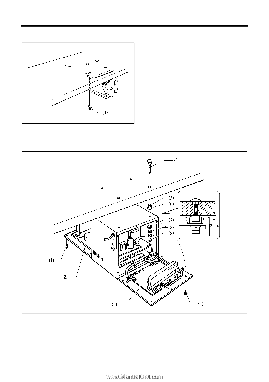
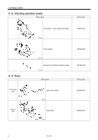
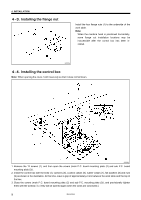
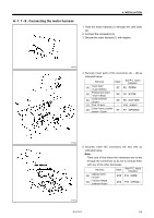
4. INSTALLATION 4-3. Installing the flange nut Install the four flange nuts (1) to the underside of the work table. Note: When the machine head is positioned horizontally, some flange nut installation locations may be inaccessible after the control box has been installed. 3857Q 4-4. Installing the control box Note: When opening the cover, hold it securely so that it does not fall down. 3858Q 1. Remove the 12 screws (1), and then open the covers (main P.C. board mounting plate (2) and sub P.C. board mounting plate (3)). 2. Install the control box with the bolts (4), cushions (5), cushion collars (6), rubber collars (7), flat washers (8) and nuts (9) as shown in the illustration. At this time, leave a gap of approximately 2 mm between the work table and the top of the box. 3. Close the covers (main P.C. board mounting plate (2) and sub P.C. mounting plate (3)), and provisionally tighten them with the screws (1). (They will be opened again when the cords are connected.) 9 HE-800A
-
 1
1 -
2
-
3
-
4
-
5
-
6
-
7
-
8
-
9
-
10
-
11
-
 12
12 -
 13
13 -
 14
14 -
 15
15 -
 16
16 -
 17
17 -
 18
18 -
 19
19 -
 20
20 -
 21
21 -
 22
22 -
23
-
24
-
25
-
26
-
27
-
28
-
29
-
30
-
31
-
32
-
33
-
34
-
35
-
36
-
37
-
38
-
39
-
40
-
41
-
42
-
43
-
44
-
45
-
46
-
47
-
48
-
49
-
50
-
51
-
52
-
53
-
54
-
55
-
56
-
57
-
58
-
59
-
60
-
61
-
62
-
63
-
64
-
65
-
66
-
67
-
68
-
69
-
70
-
71
-
72
-
73
-
74
-
75
-
76
-
77
-
78
-
79
-
80
-
81
-
82
-
83
-
84
-
85
-
86
-
87
-
88
-
89
-
90
-
91
-
92
-
93
-
94
-
95
-
96
-
97
-
98
-
99
-
100
-
101
-
102
-
103
-
104
-
105
-
106
-
107
-
108
-
109
-
110
-
111
-
112
-
113
-
114
-
115
-
116
-
117
-
118
 |
 |