Brother International HE-800A Instruction Manual - English - Page 22
Connecting the motor harness
 |
View all Brother International HE-800A manuals
Add to My Manuals
Save this manual to your list of manuals |
Page 22 highlights
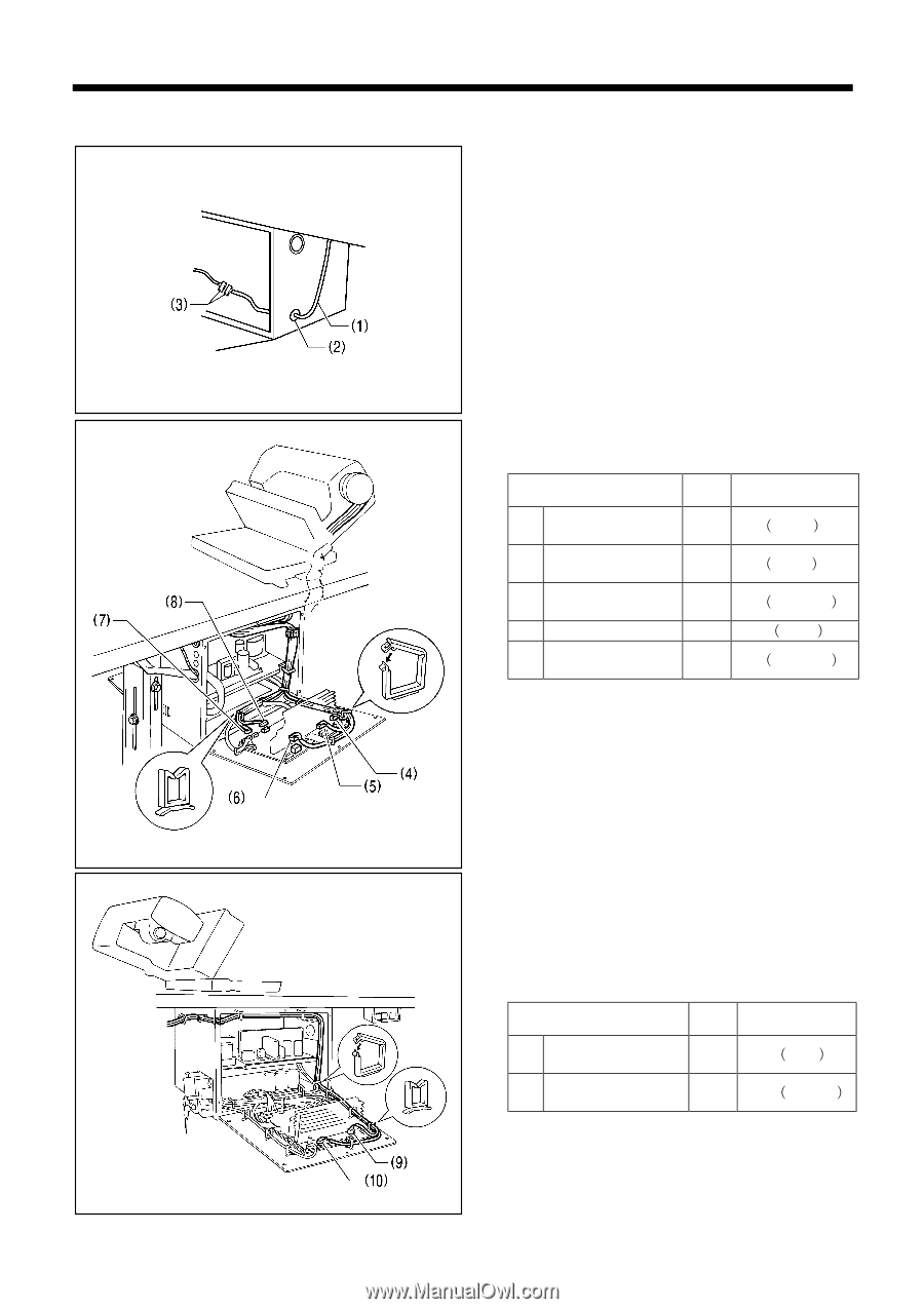
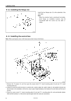
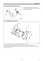
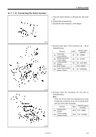
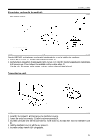
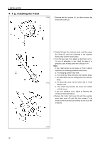
Connecting the motor harness 4. INSTALLATION 1. Pass the motor harness (1) through the cord bush (2). 2. Connect the connectors (3). 3. Secure the motor harness (1) with staples. 3869Q 4. Securely insert each of the connectors (4) - (8) as indicated below. Harness (4) Feed motor (White) Mark Sub P.C. board indication S2 P2㧔FDPM㧕 (5) Presser foot motor (Blue) S5 P5㧔FTPM㧕 (6) Cutter solenoid (7) Fan S8 P8㧔CUTTER㧕 - P10㧔FAN1㧕 (8) Cutter home position S7 P7㧔OPSEN2㧕 sensor 3870Q 5. Securely insert the connectors (9) and (10) as indicated below. Note: Take note of how these two harnesses are routed through the control box so as not to confuse them with any of the other harnesses. Harness (9) Zigzag motor (10) Tension release solenoid Mark Main P.C. board indication M16 P16㧔NPM㧕 M19 P19㧔OPSOL㧕 3871Q HE-800A 14
-
 1
1 -
2
-
3
-
4
-
5
-
6
-
7
-
8
-
9
-
10
-
11
-
12
-
13
-
14
-
15
-
16
-
 17
17 -
 18
18 -
 19
19 -
 20
20 -
 21
21 -
 22
22 -
 23
23 -
 24
24 -
 25
25 -
 26
26 -
 27
27 -
28
-
29
-
30
-
31
-
32
-
33
-
34
-
35
-
36
-
37
-
38
-
39
-
40
-
41
-
42
-
43
-
44
-
45
-
46
-
47
-
48
-
49
-
50
-
51
-
52
-
53
-
54
-
55
-
56
-
57
-
58
-
59
-
60
-
61
-
62
-
63
-
64
-
65
-
66
-
67
-
68
-
69
-
70
-
71
-
72
-
73
-
74
-
75
-
76
-
77
-
78
-
79
-
80
-
81
-
82
-
83
-
84
-
85
-
86
-
87
-
88
-
89
-
90
-
91
-
92
-
93
-
94
-
95
-
96
-
97
-
98
-
99
-
100
-
101
-
102
-
103
-
104
-
105
-
106
-
107
-
108
-
109
-
110
-
111
-
112
-
113
-
114
-
115
-
116
-
117
-
118
 |
 |