Brother International HE-800A Instruction Manual - English - Page 23
Connecting the power cord
 |
View all Brother International HE-800A manuals
Add to My Manuals
Save this manual to your list of manuals |
Page 23 highlights
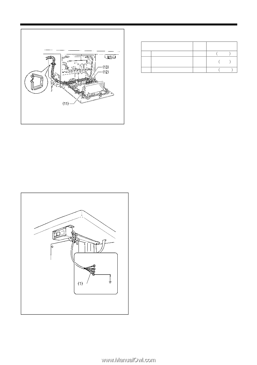
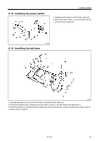
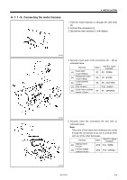
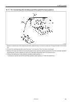
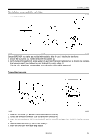
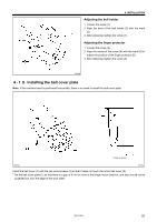
4. INSTALLATION 6. Securely insert each of the connectors (11) - (13) as indicated below. Harness Mark Main P.C. board indication (11) Synchronizer M3 P3㧔SYNC㧕 (12) Home position sensor M11 P11㧔ORG㧕 (13) Stop switch M10 P10㧔HEAD㧕 3872Q 7. Secure the harnesses inside the control box using cord clamps as shown in the illustration. Note: • Make sure that the harnesses do not come into contact with P.C. board components or with the main P.C. board heat sink or the sub-P.C. board heat sink. • Use the cord clamps at the top of the control box to adjust the harnesses so that they are not loose inside the control box, particularly when using the work table with the machine head positioned vertically. 8. Gently return the machine head to its original position. * Check that the harnesses do not touch the belt. 9. Close the covers (main P.C. board mounting plate and sub P.C. mounting plate), and tighten the 12 screws. Connecting the power cord 1. Attach an appropriate plug to the power cord (1). (The green and yellow wire is the ground wire.) 2. Insert the plug into properly-grounded AC power supply. Note: • Do not use extension cord, otherwise machine operation problems may result. • Do not connect a power supply which is not of the rated voltage, otherwise machine operation problems may result. 4027Q 15 HE-800A
-
 1
1 -
2
-
3
-
4
-
5
-
6
-
7
-
8
-
9
-
10
-
11
-
12
-
13
-
14
-
15
-
16
-
17
-
 18
18 -
 19
19 -
 20
20 -
 21
21 -
 22
22 -
 23
23 -
 24
24 -
 25
25 -
 26
26 -
 27
27 -
 28
28 -
29
-
30
-
31
-
32
-
33
-
34
-
35
-
36
-
37
-
38
-
39
-
40
-
41
-
42
-
43
-
44
-
45
-
46
-
47
-
48
-
49
-
50
-
51
-
52
-
53
-
54
-
55
-
56
-
57
-
58
-
59
-
60
-
61
-
62
-
63
-
64
-
65
-
66
-
67
-
68
-
69
-
70
-
71
-
72
-
73
-
74
-
75
-
76
-
77
-
78
-
79
-
80
-
81
-
82
-
83
-
84
-
85
-
86
-
87
-
88
-
89
-
90
-
91
-
92
-
93
-
94
-
95
-
96
-
97
-
98
-
99
-
100
-
101
-
102
-
103
-
104
-
105
-
106
-
107
-
108
-
109
-
110
-
111
-
112
-
113
-
114
-
115
-
116
-
117
-
118
 |
 |