Canon imageFORMULA DR-3010C Compact Workgroup Scanner User Manual - Page 10
Names and Functions of Parts
 |
View all Canon imageFORMULA DR-3010C Compact Workgroup Scanner manuals
Add to My Manuals
Save this manual to your list of manuals |
Page 10 highlights
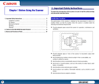
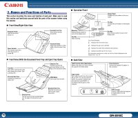
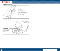
3. Names and Functions of Parts This section describes the name and function of each part. Make sure to read this section and familiarize yourself with the parts of the scanner before using the scanner. „ Front View/Right-Side View „ Operation Panel Display Panel Displays the job numbers or the error codes. Plus Key Increases the job number on the display panel. Document Feeder Load the Document. (See p.21.) Document Feed Tray Attach before placing documents. Power Indicator This indicator lights blue when the scanner is turned ON. Document Guides Adjust these guides to fit the width of the document. (See p.22.) „ Front View (With the Document Feed Tray and Eject Tray Open) Front Unit Open when clearing paper jams and cleaning the scanner. (See p.34 and p.67.) Document Eject Area Scanned documents are output here. Extension Tray Pull this tray out if the document hangs over the edge of the document feeder. OPEN Button Use to open the front unit. Extension Tray Pull this tray out if the document hangs over the edge of the document eject tray. Document Eject Tray Open this tray when you want to stack output documents. Minus Key Reduces the job number to scan on the display panel. Stop Key Stops scanning. Start Key Starts the job number to scan on the display panel. Error Codes Displayed: : Displayed if the front unit is open. : Displayed if a paper jam is detected. : Displayed if a double feed is detected while scanning. : Displayed if another type of error occurs. For information resolving error codes, see "An Error Code Is Displayed on the Display Panel," on p.78. „ Back View Theft Prevention Hole (Kensington) Attach a key chain, etc. here to prevent the scanner from being stolen. Power Connector Connect the supplied AC adapter to this connector. Power Switch This switch is used to turn the scanner ON and OFF. If you set the switch to 'AUTO', the scanner is linked to be automatically turned ON/OFF in accordance with the power of the computer. USB Connector Connect a USB cable that supports Hi-Speed USB 2.0 to this connector. 10 DR-3010C
-
 1
1 -
2
-
3
-
4
-
 5
5 -
 6
6 -
 7
7 -
 8
8 -
 9
9 -
 10
10 -
 11
11 -
 12
12 -
 13
13 -
 14
14 -
 15
15 -
16
-
17
-
18
-
19
-
20
-
21
-
22
-
23
-
24
-
25
-
26
-
27
-
28
-
29
-
30
-
31
-
32
-
33
-
34
-
35
-
36
-
37
-
38
-
39
-
40
-
41
-
42
-
43
-
44
-
45
-
46
-
47
-
48
-
49
-
50
-
51
-
52
-
53
-
54
-
55
-
56
-
57
-
58
-
59
-
60
-
61
-
62
-
63
-
64
-
65
-
66
-
67
-
68
-
69
-
70
-
71
-
72
-
73
-
74
-
75
-
76
-
77
-
78
-
79
-
80
-
81
-
82
-
83
-
84
-
85
-
86
-
87
 |
 |
