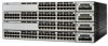
Cisco WS-C3750X-24T-L Hardware Installation Guide
Cisco WS-C3750X-24T-L Manual
 |
View all Cisco WS-C3750X-24T-L manuals
Add to My Manuals
Save this manual to your list of manuals |
Cisco WS-C3750X-24T-L manual content summary:
- Cisco WS-C3750X-24T-L | Hardware Installation Guide - Page 1
this access method: Cisco.com CD-ROM Printed manuals Other: 8 I use the following three product features the most: Document Information Document Title: Catalyst 3750 Switch Hardware Installation Guide Part Number: 78-15136-02 S/W Release (if applicable): On a scale of - Cisco WS-C3750X-24T-L | Hardware Installation Guide - Page 2
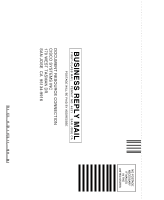
NO POSTAGE NECESSARY IF MAILED IN THE UNITED STATES BUSINESS REPLY MAIL FIRST-CLASS MAIL PERMIT NO. 4631 SAN JOSE CA POSTAGE WILL BE PAID BY ADDRESSEE DOCUMENT RESOURCE CONNECTION CISCO SYSTEMS INC 170 WEST TASMAN DR SAN JOSE CA 95134-9916 - Cisco WS-C3750X-24T-L | Hardware Installation Guide - Page 3
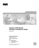
Catalyst 3750 Switch Hardware Installation Guide August 2003 Corporate Headquarters Cisco Systems, Inc. 170 West Tasman Drive San Jose, CA 95134-1706 USA http://www.cisco.com Tel: 408 526-4000 800 553-NETS (6387) Fax: 408 526-4100 Customer Order Number: DOC-7815136= Text Part Number: 78-15136-02 - Cisco WS-C3750X-24T-L | Hardware Installation Guide - Page 4
in this manual generates and may radiate radio-frequency energy. If it is not installed in accordance with Cisco's installation instructions, it radio. • Plug the equipment into an outlet that is on a different circuit from the television or radio. (That is, make certain the equipment and the - Cisco WS-C3750X-24T-L | Hardware Installation Guide - Page 5
in this document or Web site are the property of their respective owners. The use of the word partner does not imply a partnership relationship between Cisco and any other company. (0304R) Catalyst 3750 Switch Hardware Installation Guide Copyright © 2003, Cisco Systems, Inc. All rights reserved. - Cisco WS-C3750X-24T-L | Hardware Installation Guide - Page 6
- Cisco WS-C3750X-24T-L | Hardware Installation Guide - Page 7
xxvii Obtaining Additional Publications and Information xxviii Using Express Setup 1-1 Taking Out What You Need 1-2 Powering On the Switch 1-3 Starting Express Setup 1-4 Configuring the Switch Settings 1-9 Verifying Switch IP Address (Optional) 1-10 Catalyst 3750 Switch Hardware Installation Guide v - Cisco WS-C3750X-24T-L | Hardware Installation Guide - Page 8
2-16 Internal Power Supply Connector 2-16 Cisco RPS Connector 2-16 Console Port 2-17 Management Options 2-18 Network Configurations 2-19 Switch Installation 3-1 Preparing for Installation 3-1 Warnings 3-2 EMC Regulatory Statements 3-4 Catalyst 3750 Switch Hardware Installation Guide vi 78-15136 - Cisco WS-C3750X-24T-L | Hardware Installation Guide - Page 9
Port 3-11 Planning the Stack 3-12 Planning Considerations 3-12 Powering Considerations 3-13 Cabling Considerations 3-14 Recommended Cabling Configurations 3-15 Installing the Switch 3-17 Rack Mounting 3-18 Removing Screws from the Switch 3-19 Attaching Brackets to the Catalyst 3750G-24TS Switch - Cisco WS-C3750X-24T-L | Hardware Installation Guide - Page 10
B-2 10/100 Ports B-3 SFP Module Ports B-5 Console Port B-6 Cable and Adapter Specifications B-6 Two Twisted-Pair Cable Pinouts B-6 Four Twisted-Pair Cable Pinouts for 10/100 Ports B-7 Four Twisted-Pair Cable Pinouts for 1000BASE-T Ports B-8 Catalyst 3750 Switch Hardware Installation Guide viii 78 - Cisco WS-C3750X-24T-L | Hardware Installation Guide - Page 11
(Optional) D-5 Connecting to the Console Port D-7 Starting the Terminal Emulation Software D-9 Connecting to a Power Source D-9 Entering the Initial Configuration Information D-10 IP Settings D-10 Completing the Setup Program D-11 78-15136-02 Catalyst 3750 Switch Hardware Installation Guide ix - Cisco WS-C3750X-24T-L | Hardware Installation Guide - Page 12
for Rack-Mounting and Servicing E-19 Redundant Power Supply Connection Warning E-24 Switch Installation Warning E-25 Restricted Area E-27 Ethernet Cable Shielding in Offices E-28 Laser Beam Exposure E-30 Laser Radiation E-31 E-32 Catalyst 3750 Switch Hardware Installation Guide x 78-15136-02 - Cisco WS-C3750X-24T-L | Hardware Installation Guide - Page 13
your hardware warranty and various services that you can use during the warranty period. Follow these steps to access and download the Cisco Information Packet and your warranty document from Cisco.com from Adobe's website: http://www.adobe.com Catalyst 3750 Switch Hardware Installation Guide xi - Cisco WS-C3750X-24T-L | Hardware Installation Guide - Page 14
the Cisco service and support website for assistance: http://www.cisco.com/public/Support_root.shtml. Duration of Hardware Warranty A Cisco product hardware warranty is supported for as long as the original end user continues to own or use the product, provided that the fan and power supply warranty - Cisco WS-C3750X-24T-L | Hardware Installation Guide - Page 15
your Cisco Sales and Service Representative. Complete the information below, and keep it for reference. Company product purchased from Company telephone number Product model number Product serial number Maintenance contract number 78-15136-02 Catalyst 3750 Switch Hardware Installation Guide xiii - Cisco WS-C3750X-24T-L | Hardware Installation Guide - Page 16
Cisco Limited Lifetime Hardware Warranty Terms Catalyst 3750 Switch Hardware Installation Guide xiv 78-15136-02 - Cisco WS-C3750X-24T-L | Hardware Installation Guide - Page 17
12.1 commands, refer to the IOS documentation set from the Cisco.com home page at Service and Support > Technical Documents. On the Cisco Product Documentation home page, select Release 12.1 from the Cisco IOS Software drop-down list. 78-15136-02 Catalyst 3750 Switch Hardware Installation Guide xv - Cisco WS-C3750X-24T-L | Hardware Installation Guide - Page 18
at the end of each warning to locate its translation in the translated safety warnings that accompanied this device. SAVE THESE INSTRUCTIONS Waarschuwing die bij het apparaat wordt geleverd, wilt raadplegen. BEWAAR DEZE INSTRUCTIES Catalyst 3750 Switch Hardware Installation Guide xvi 78-15136-02 - Cisco WS-C3750X-24T-L | Hardware Installation Guide - Page 19
éro de l'instruction situé à Ende jeder Warnung angegebenen Anweisungsnummer nach der jeweiligen Übersetzung in den übersetzten Sicherheitshinweisen, die zusammen mit diesem Gerät ausgeliefert wurden. BEWAHREN SIE DIESE HINWEISE GUT AUF. 78-15136-02 Catalyst 3750 Switch Hardware Installation Guide - Cisco WS-C3750X-24T-L | Hardware Installation Guide - Page 20
instrução fornecido ao final de cada aviso para localizar sua tradução nos avisos de segurança traduzidos que acompanham este dispositivo. GUARDE ESTAS INSTRUÇÕES xviii Catalyst 3750 Switch Hardware Installation Guide 78-15136-02 - Cisco WS-C3750X-24T-L | Hardware Installation Guide - Page 21
som finns i slutet av varje varning för att hitta dess översättning i de översatta säkerhetsvarningar som medföljer denna anordning. SPARA DESSA ANVISNINGAR 78-15136-02 Catalyst 3750 Switch Hardware Installation Guide xix - Cisco WS-C3750X-24T-L | Hardware Installation Guide - Page 22
Conventions Preface Catalyst 3750 Switch Hardware Installation Guide xx 78-15136-02 - Cisco WS-C3750X-24T-L | Hardware Installation Guide - Page 23
Catalyst 3750 Switch (not orderable but available on Cisco.com) Note Before installing, configuring, or upgrading the switch, refer to the release notes on Cisco.com for the latest information. • Catalyst 3750 Switch Software Configuration Guide (order number DOC-7815164=) • Catalyst 3750 Switch - Cisco WS-C3750X-24T-L | Hardware Installation Guide - Page 24
: http://www.cisco.com/univercd/cc/td/doc/es_inpck/pdi.htm You can order Cisco documentation in these ways: • Registered Cisco.com users (Cisco direct customers) can order Cisco product documentation from the Networking Products MarketPlace: Catalyst 3750 Switch Hardware Installation Guide xxii 78 - Cisco WS-C3750X-24T-L | Hardware Installation Guide - Page 25
Cisco TAC website (http://www.cisco.com/tac) provides online documents and tools for troubleshooting and resolving technical issues with Cisco products and technologies. The Cisco TAC website is available 24 hours a day, 365 days a year. 78-15136-02 Catalyst 3750 Switch Hardware Installation Guide - Cisco WS-C3750X-24T-L | Hardware Installation Guide - Page 26
established case priority definitions. Priority 1 (P1)-Your network is "down" or there is a critical impact to your business operations. You and Cisco will commit all necessary resources around the clock to resolve the situation. xxiv Catalyst 3750 Switch Hardware Installation Guide 78-15136-02 - Cisco WS-C3750X-24T-L | Hardware Installation Guide - Page 27
troubleshooting tips, configuration examples, customer case studies, tutorials and training, certification information, and links to numerous in-depth online resources. You can access Packet magazine at this URL: http://www.cisco.com/go/packet 78-15136-02 Catalyst 3750 Switch Hardware Installation - Cisco WS-C3750X-24T-L | Hardware Installation Guide - Page 28
about/ac123/ac147/about_cisco_the_internet_ protocol_journal.html • Training-Cisco offers world-class networking training. Current offerings in network training are listed at this URL: http://www.cisco.com/en/US/learning/index.html xxvi Catalyst 3750 Switch Hardware Installation Guide 78-15136-02 - Cisco WS-C3750X-24T-L | Hardware Installation Guide - Page 29
or a switch stack. Note Express Setup is supported on switches running Cisco IOS Release 12.1(14)EA1 or later. If you are installing a new switch, refer to the Cisco IOS release label on the rear panel of the switch to determine the release. For quick setup instructions for switches running releases - Cisco WS-C3750X-24T-L | Hardware Installation Guide - Page 30
12X 14X 23X Catalyst 3750 SERIES 24X 97175 2 1 Switch 2 AC power cord You also need to provide an Ethernet (Category 5) straight-through cable (not included), as shown in Figure 1-2, to connect the switch to your PC or workstation. Catalyst 3750 Switch Hardware Installation Guide 1-2 78-15136 - Cisco WS-C3750X-24T-L | Hardware Installation Guide - Page 31
the switch rear panel, as shown in Figure 1-3. Figure 1-3 Connecting the Power 1 STACK 1 STACK 2 CONSOLE 1.2A-100R>06A-A2T4,IN05GV0-~60 HZ DSCPIENPCPO+IUWF1T2IEESvDRFISO@NUR1MP3RPAAELNYMUOATLE 97176 1 Switch 2 2 AC power cord 78-15136-02 Catalyst 3750 Switch Hardware Installation Guide 1-3 - Cisco WS-C3750X-24T-L | Hardware Installation Guide - Page 32
connected to the switch. The switch acts as a DHCP server during the Express Setup procedure, and only the PC or workstation connected to the switch after Express Startup is started should receive a DHCP address from the switch. Catalyst 3750 Switch Hardware Installation Guide 1-4 78-15136-02 - Cisco WS-C3750X-24T-L | Hardware Installation Guide - Page 33
Address and Configuration" section on page 4-2. Step 4 Connect the Ethernet cable (not included) to a 10/100 Ethernet port or small form-factor pluggable (SFP) module port on the front panel of the switch, as shown in Figure 1-5. 78-15136-02 Catalyst 3750 Switch Hardware Installation Guide 1-5 - Cisco WS-C3750X-24T-L | Hardware Installation Guide - Page 34
configure it. Figure 1-5 Connecting the Switch and PC or Workstation Ethernet Ports 1 SYST RPS MASTR STAT 1X DUPLX SPEED STACK MODE 2X 11X 13X 12X 14X 23X Catalyst 3750 SERIES 24X 2 97174 3 1 Switch 2 Ethernet cable 3 PC or workstation Step 5 Step 6 Step 7 Connect the other end - Cisco WS-C3750X-24T-L | Hardware Installation Guide - Page 35
the browser, and press Enter. • Did you enter the wrong address in the browser, or is there an error message displayed in the browser window? Catalyst 3750 Switch Hardware Installation Guide 1-7 - Cisco WS-C3750X-24T-L | Hardware Installation Guide - Page 36
explains how to configure a switch by using the Express Setup web page. To configure the switch by using the command-line interface (CLI)-based setup program, see Appendix D, "Quick Setup By Using the CLI-Based Setup Program." Catalyst 3750 Switch Hardware Installation Guide 1-8 78-15136-02 - Cisco WS-C3750X-24T-L | Hardware Installation Guide - Page 37
system contact in the System Contact field. This identifies the system administrator for the switch or network. (Optional) Enter your system location in the System Location field. This identifies the physical location of the switch. 78-15136-02 Catalyst 3750 Switch Hardware Installation Guide 1-9 - Cisco WS-C3750X-24T-L | Hardware Installation Guide - Page 38
configured on your switch: Step 1 Step 2 Launch a web browser on a PC or workstation that is connected the network. Enter the IP address of your switch (for example: 172.20.139.142.) The switch home page appears, as shown in Figure 1-8. 1-10 Catalyst 3750 Switch Hardware Installation Guide - Cisco WS-C3750X-24T-L | Hardware Installation Guide - Page 39
you have entered a wrong IP address or need to change the IP address of your switch, you can clear the IP address on your switch by following the steps in the "Clearing the Switch IP Address and Configuration" section on page 4-2. 78-15136-02 Catalyst 3750 Switch Hardware Installation Guide 1-11 - Cisco WS-C3750X-24T-L | Hardware Installation Guide - Page 40
Access Catalyst 3750 documentation. Installing or Connecting Devices to the Switch For detailed installation procedures on mounting your switch on or under a desk or on a wall, or connecting devices to the switch, see Chapter 3, "Installation." 1-12 Catalyst 3750 Switch Hardware Installation Guide - Cisco WS-C3750X-24T-L | Hardware Installation Guide - Page 41
backbone switches, aggregating 10BASE-T, 100BASE-TX, and 1000BASE-T Ethernet traffic from other network devices. Refer to the switch software configuration guide for examples showing how you might deploy the switches in your network. 78-15136-02 Catalyst 3750 Switch Hardware Installation Guide 2-1 - Cisco WS-C3750X-24T-L | Hardware Installation Guide - Page 42
are hot-swappable • Power redundancy - Connection for optional Cisco RPS 300 redundant power system that operates on AC input and supplies backup DC power output to the Catalyst 3750-24TS, 3750G-24T, 3750-48TS, and 3750G-12S switches. Catalyst 3750 Switch Hardware Installation Guide 2-2 78-15136 - Cisco WS-C3750X-24T-L | Hardware Installation Guide - Page 43
not support the Catalyst 3750G-24TS switch. - Connection for optional Cisco RPS 675 redundant power system that operates on AC input and supplies backup DC power output to the family of Catalyst 3750 switches. Front Panel Description The Catalyst 3750-24TS 10/100 ports are numbered 1 through 24. The - Cisco WS-C3750X-24T-L | Hardware Installation Guide - Page 44
22 23 24 23X 14X 24X Catalyst 3750 SERIES 25 26 27 28 1 2 1 10/100 ports 2 SFP module ports The Catalyst 3750G-12S SFP module slots are numbered 1 through 12. The ports are grouped in three sets of four, as shown in Figure 2-4. Catalyst 3750 Switch Hardware Installation Guide 2-4 78-15136 - Cisco WS-C3750X-24T-L | Hardware Installation Guide - Page 45
15 16 17 18 15X 17X 16X 18X 19 20 21 22 23 24 25 26 27 28 29 30 31 32 33 34 31X 33X 35 36 37 38 39 40 41 42 43 44 45 46 47 48 47X 32X 34X 48X Catalyst 3750 SERIES 1 3 2 4 1 2 1 10/100 ports 2 SFP module ports 78-15136-02 Catalyst 3750 Switch Hardware Installation Guide 2-5 - Cisco WS-C3750X-24T-L | Hardware Installation Guide - Page 46
of device on the other end of the connection. The automatic crossover feature is disabled by default. For configuration information for this feature, refer to the switch software configuration guide or the switch command reference. Catalyst 3750 Switch Hardware Installation Guide 2-6 78-15136-02 - Cisco WS-C3750X-24T-L | Hardware Installation Guide - Page 47
45 connectors to connect to a copper SFP module. The Catalyst 3750 models support these Cisco SFP options: • 1000BASE-LX • 1000BASE-SX • 1000BASE-T For more information about these SFP modules, refer to your SFP module documentation. 78-15136-02 Catalyst 3750 Switch Hardware Installation Guide 2-7 - Cisco WS-C3750X-24T-L | Hardware Installation Guide - Page 48
Figure 2-6 Catalyst 3750 LEDs SYST RPS MASTR STAT DUPLX SPEED STACK MODE 12345678 9 12 1X 34 56 78 9 10 11 12 11X 2X 12X 1 Mode button 2 Stack LED 3 Speed LED 4 Duplex LED 5 Status LED 6 Master LED 7 RPS LED 8 System LED 9 Port LED 86545 Catalyst 3750 Switch Hardware Installation Guide - Cisco WS-C3750X-24T-L | Hardware Installation Guide - Page 49
should turn green. If it does not, the RPS fan could have failed. Contact Cisco Systems. The internal power supply in a switch has failed, and the RPS is providing power to the switch (redundancy has been allocated to this device). 78-15136-02 Catalyst 3750 Switch Hardware Installation Guide 2-9 - Cisco WS-C3750X-24T-L | Hardware Installation Guide - Page 50
Power System Hardware Installation Guide. For more information about the Cisco RPS 675, refer to the Cisco RPS 675 Redundant Power System Hardware Installation Guide. Note The Cisco RPS 300 does not support the Catalyst 3750G-24TS switches. Master LED The Master LED shows the stack master - Cisco WS-C3750X-24T-L | Hardware Installation Guide - Page 51
for up to 30 seconds as STP checks the switch for possible loops. Flashing amber Port is blocked by STP and is transmitting or receiving packets. Off Port is operating in half duplex. Green Port is operating in full duplex. 78-15136-02 Catalyst 3750 Switch Hardware Installation Guide 2-11 - Cisco WS-C3750X-24T-L | Hardware Installation Guide - Page 52
the StackWise ports (on the switch rear panel) are up, and the representative stack LEDs are amber when the ports are down: • SFP port LEDs 1 and 2 on the Catalyst 3750-24TS switch show the status for StackWise ports 1 and 2, respectively. 2-12 Catalyst 3750 Switch Hardware Installation Guide 78 - Cisco WS-C3750X-24T-L | Hardware Installation Guide - Page 53
• SFP port LEDs 3 and 4 on the Catalyst 3750-48TS switch show the status for StackWise ports 1 and 2, respectively. • SFP port LEDs 27 and 28 on the Catalyst 3750G-24TS switch show the status for StackWise ports 1 and 2, respectively. • The 10/100/1000 port LEDs 23 and 24 on the Catalyst 3750G-24T - Cisco WS-C3750X-24T-L | Hardware Installation Guide - Page 54
3750-48TS Rear Panel 86548 STACK 1 STACK 2 CONSOLE 1.6A-100R>09A-A2T0,IN05GV0-~60 HZ [email protected] 1 23 4 5 1 StackWise ports 2 RJ-45 console port 3 Fan exhaust 4 AC power connector 5 RPS connector 2-14 Catalyst 3750 Switch Hardware Installation - Cisco WS-C3750X-24T-L | Hardware Installation Guide - Page 55
to other nonapproved Cisco cables or equipment. You can order these StackWise cables from your Cisco sales representative: • CAB-STACK-50CM= (0.5-meter cable) • CAB-STACK-1M= (1-meter cable) • CAB-STACK-3M= (3-meter cable) 78-15136-02 Catalyst 3750 Switch Hardware Installation Guide 2-15 - Cisco WS-C3750X-24T-L | Hardware Installation Guide - Page 56
power of 300W. Use the supplied RPS connector cable to connect the RPS to the switch. Note The Cisco RPS 300 does not support the Catalyst 3750G-24TS switches. Warning Attach only the Cisco RPS (model PWR300-AC-RPS-N1) to the RPS receptacle. 2-16 Catalyst 3750 Switch Hardware Installation Guide - Cisco WS-C3750X-24T-L | Hardware Installation Guide - Page 57
to the Cisco RPS 300 Redundant Power System Hardware Installation Guide. The Cisco RPS 675 has two output levels: -48V and 12V with a total maximum output power of 675W. Use the supplied RPS connector cable to connect the RPS to the switch. Warning Attach only the Cisco RPS (model PWR675-AC-RPS-N1 - Cisco WS-C3750X-24T-L | Hardware Installation Guide - Page 58
Management Information Base (MIB) extensions and four Remote Monitoring (RMON) groups. Refer to the switch software configuration guide on Cisco.com and the documentation that came with your SNMP application for more information. 2-18 Catalyst 3750 Switch Hardware Installation Guide 78-15136-02 - Cisco WS-C3750X-24T-L | Hardware Installation Guide - Page 59
to the switch software configuration guide on Cisco.com for network configuration concepts and examples of using the switch to create dedicated network segments and interconnecting the segments through Gigabit Ethernet connections. 78-15136-02 Catalyst 3750 Switch Hardware Installation Guide 2-19 - Cisco WS-C3750X-24T-L | Hardware Installation Guide - Page 60
Management Options Chapter 2 Product Overview 2-20 Catalyst 3750 Switch Hardware Installation Guide 78-15136-02 - Cisco WS-C3750X-24T-L | Hardware Installation Guide - Page 61
3-44 • Connecting to an SFP Module, page 3-46 • Where to Go Next, page 3-50 Preparing for Installation This section covers these topics: • Warnings, page 3-2 • EMC Regulatory Statements, page 3-4 • Installation Guidelines, page 3-6 78-15136-02 Catalyst 3750 Switch Hardware Installation Guide 3-1 - Cisco WS-C3750X-24T-L | Hardware Installation Guide - Page 62
Do not stack the chassis on any other equipment. If the chassis falls, it can cause severe bodily injury and equipment damage. Warning The plug-socket combination must be accessible at all times because it serves as the main disconnecting device. Catalyst 3750 Switch Hardware Installation Guide - Cisco WS-C3750X-24T-L | Hardware Installation Guide - Page 63
product should be handled according to all national laws and regulations. Warning Attach only the Cisco RPS (model PWR675-AC-RPS-N1) to the RPS receptacle. Warning Class 1 laser product Warning Avoid exposure to the laser beam. 78-15136-02 Catalyst 3750 Switch Hardware Installation Guide 3-3 - Cisco WS-C3750X-24T-L | Hardware Installation Guide - Page 64
for Interference by Information Technology Equipment (VCCI). If this equipment is used in a domestic environment, radio disturbance may arise. When such trouble occurs, the user may be required to take corrective actions. 46464 Catalyst 3750 Switch Hardware Installation Guide 3-4 78-15136-02 - Cisco WS-C3750X-24T-L | Hardware Installation Guide - Page 65
should be replaced with a residential-use type. Class A Notice for Hungary Warning This equipment is a class A product and should be used and installed properly of installation and protection distance are used. Statement 256 78-15136-02 Catalyst 3750 Switch Hardware Installation Guide 3-5 - Cisco WS-C3750X-24T-L | Hardware Installation Guide - Page 66
end of the cable, and the cable must not exceed the stipulated cable length for reliable communications. Table 3-1 Fiber-Optic SFP Module Port Cabling Specifications SFP . - Access to ports is sufficient for unrestricted cabling. Catalyst 3750 Switch Hardware Installation Guide 3-6 78-15136-02 - Cisco WS-C3750X-24T-L | Hardware Installation Guide - Page 67
your Cisco representative or reseller for support. Return all packing material to the shipping container, and save it. The switch is shipped with these items: • This Catalyst 3750 Switch Hardware Installation Guide • About the Catalyst 3750 Documentation flyer • AC power cord (AC-powered switches - Cisco WS-C3750X-24T-L | Hardware Installation Guide - Page 68
to the switch (Catalyst 3750-24TS, 3750G-24T, and 3750-48TS switches) - Four Phillips machine screws for attaching the brackets to a rack - One cable guide and one black Phillips machine screw for attaching the cable guide to one of the mounting brackets - One redundant power system (RPS) connector - Cisco WS-C3750X-24T-L | Hardware Installation Guide - Page 69
port, as shown in Figure 3-1. Attach the DB-9 female DTE adapter of the RJ-45-to-DB-9 adapter cable to a PC, or attach an appropriate adapter to the terminal. Start the terminal-emulation program if you are using a PC or terminal. 78-15136-02 Catalyst 3750 Switch Hardware Installation Guide - Cisco WS-C3750X-24T-L | Hardware Installation Guide - Page 70
management station. See the "Connecting a PC or Terminal to the Console Port" section on page 3-8 for information on connecting to the switch console port. Connect one end of the AC power cord to the AC power connector on the switch. Catalyst 3750 Switch Hardware Installation Guide 78-15136-02 - Cisco WS-C3750X-24T-L | Hardware Installation Guide - Page 71
end of the power cord to an AC power outlet. If you are installing the Catalyst 3750-24TS, 3750G-24T, 3750G-12S, or 3750-48TS switches, you can use the Cisco RPS 300. Warning Attach only the Cisco RPS 300 (model PWR300-AC-RPS-N1) to the RPS receptacle If you are installing the Catalyst 3750-24TS - Cisco WS-C3750X-24T-L | Hardware Installation Guide - Page 72
to stack the switches. If you do not have access to the rear panel, make sure you cable the switches before you rack-mount them. • For concepts and procedures to manage switch stacks, refer to the switch software configuration guide. 3-12 Catalyst 3750 Switch Hardware Installation Guide 78 - Cisco WS-C3750X-24T-L | Hardware Installation Guide - Page 73
remove it from an existing switch stack. Note For conditions that can cause a stack master re-election or to manually elect the stack master, refer to the "Managing Switch Stacks" chapter in the switch software configuration guide. 78-15136-02 Catalyst 3750 Switch Hardware Installation Guide 3-13 - Cisco WS-C3750X-24T-L | Hardware Installation Guide - Page 74
3 Switch Installation Cabling Considerations The illustrations in this section display cabling configuration examples that show the stack bandwidth and possible stack partitioning. Figure 3-2 shows an example of a stack of Catalyst 3750 switches that provides full bandwidth and redundant StackWise - Cisco WS-C3750X-24T-L | Hardware Installation Guide - Page 75
Figure 3-6 is an example of a recommended configuration using the supplied 0.5-meter StackWise cable. In this example, the switches are stacked in a vertical rack or on a table. This configuration provides redundant connections. 78-15136-02 Catalyst 3750 Switch Hardware Installation Guide 3-15 - Cisco WS-C3750X-24T-L | Hardware Installation Guide - Page 76
to the supplied 0.5-meter StackWise cable. This configuration also provides redundant connections. Figure 3-7 Stacking the Catalyst 3750 Switches in a Vertical Rack or on a Table Using 0.5-meter and 3-meter StackWise Cables 86585 3-16 Catalyst 3750 Switch Hardware Installation Guide 78-15136 - Cisco WS-C3750X-24T-L | Hardware Installation Guide - Page 77
Nine Switches in a Side-by-Side Mounting Configuration 90532 Installing the Switch This section describes these installation procedures: • Rack Mounting, page 3-18 • Wall Mounting, page 3-32 • Table or Shelf Mounting, page 3-36 78-15136-02 Catalyst 3750 Switch Hardware Installation Guide 3-17 - Cisco WS-C3750X-24T-L | Hardware Installation Guide - Page 78
the 24-inch rack-mounting brackets and hardware from Cisco. For the Catalyst 3750G-24TS switches, order part number RCKMNT-3550-1.5RU=. For the Catalyst 3750-24TS, 3750G-24T, 3750G-12S, and 3750-48TS switches, order part number RCKMNT-1RU=. 3-18 Catalyst 3750 Switch Hardware Installation Guide 78 - Cisco WS-C3750X-24T-L | Hardware Installation Guide - Page 79
3750-24TS, 3750G-24T, and 3750-48TS Switches 86819 16 17 18 19 20 21 22 23 24 23X Catalyst 3750 SERIES 1 24X 2 Figure 3-11 Removing Screws from the Catalyst 3750G-12S Switch 97170 16 8 9 10 Catalyst 3750 SERIES 11 12 78-15136-02 Catalyst 3750 Switch Hardware Installation Guide - Cisco WS-C3750X-24T-L | Hardware Installation Guide - Page 80
700-11523-XX; for 24-inch racks, use part number 700-12398-XX. Figure 3-13 through Figure 3-18 show how to attach each type bracket to one side of the switch. Follow the same steps to attach the second bracket to the opposite side. 3-20 Catalyst 3750 Switch Hardware Installation Guide 78-15136-02 - Cisco WS-C3750X-24T-L | Hardware Installation Guide - Page 81
Brackets for 19-inch Racks, Front Panel Forward 1 Installing the Switch SYST RPS MASTR STAT DUPLX SPEED STACK MODE 1 Phillips flat-head screws 12 1X 34 56 78 9 10 11 12 11X 2X 12X 13 14 15 16 13X 17 14X 86839 78-15136-02 Catalyst 3750 Switch Hardware Installation Guide 3-21 - Cisco WS-C3750X-24T-L | Hardware Installation Guide - Page 82
the Switch Chapter 3 Switch Installation Figure 3-14 Attaching Brackets for 24-Inch Racks, Front Panel Forward 1 SYST RPS MASTR STAT DUPLX SPEED STACK MODE 1 Phillips flat-head screws 12 1X 34 56 78 9 10 11 12 11X 2X 12X 86557 3-22 Catalyst 3750 Switch Hardware Installation Guide 78 - Cisco WS-C3750X-24T-L | Hardware Installation Guide - Page 83
@NUR1MP7RPAaELNYMUOATLE 1 1 Phillips flat-head screws Figure 3-16 Attaching Brackets for 24-Inch Racks, Rear Panel Forward DSCPIENPCPO+IUWF1TI2EESvDRFISO@NUR1MP7RPAaELNYMUOATLE 1 Phillips flat-head screws 78-15136-02 1 86556 Catalyst 3750 Switch Hardware Installation Guide 3-23 - Cisco WS-C3750X-24T-L | Hardware Installation Guide - Page 84
Figure 3-18 Attaching Brackets for 24-Inch Telco Racks 13 14 13X 15 16 17 18 19 20 21 22 23 24 23X 14X 24X Catalyst 3750 SERIES 25 26 27 28 1 Phillips flat-head screws Chapter 3 Switch Installation 1 1 86558 86559 3-24 Catalyst 3750 Switch Hardware Installation Guide 78-15136-02 - Cisco WS-C3750X-24T-L | Hardware Installation Guide - Page 85
bracket to the opposite side. Figure 3-19 Attaching Brackets for 19-Inch Racks, Front Panel Forward 1 SYST RPS MASTR STAT DUPLX SPEED STACK MODE 1 Phillips flat-head screws 12 1X 34 56 78 9 10 11 12 11X 2X 12X 86560 78-15136-02 Catalyst 3750 Switch Hardware Installation Guide 3-25 - Cisco WS-C3750X-24T-L | Hardware Installation Guide - Page 86
Installing the Switch Chapter 3 Switch Installation Figure 3-20 Attaching Brackets for 24-Inch Racks, Front Panel Forward 1 86561 SYST RPS MASTR STAT DUPLX SPEED STACK MODE 1 Phillips flat 1 1 Phillips flat-head screws 86562 3-26 Catalyst 3750 Switch Hardware Installation Guide 78-15136-02 - Cisco WS-C3750X-24T-L | Hardware Installation Guide - Page 87
for 19-Inch Telco Racks to Catalyst 3750-24TS, 3750G-24T, and 3750-48TS Switches 9 10 11 12 11X 12X 13 14 13X 15 16 17 18 19 20 21 22 23 24 23X 14X 24X Catalyst 3750 SERIES 1 2 1 1 Phillips flat-head screws 86564 78-15136-02 Catalyst 3750 Switch Hardware Installation Guide 3-27 - Cisco WS-C3750X-24T-L | Hardware Installation Guide - Page 88
-head screws Mounting the Switch in a Rack After the brackets are attached to the switch, use the four supplied number-12 Phillips machine screws to securely attach the brackets to the rack, as shown in Figure 3-26 and Figure 3-27. 3-28 Catalyst 3750 Switch Hardware Installation Guide 78-15136-02 - Cisco WS-C3750X-24T-L | Hardware Installation Guide - Page 89
19 20 21 22 23 24 23X 14X 24X Catalyst 3750 SERIES 25 26 27 28 86566 1 Phillips machine screws Figure 3-27 Mounting the Catalyst 3750-24TS, 3750G-24T, 3750G-12S, and 3750-48TS Switches in a Rack SYST RPS MASTR STAT DUPLX SPYESETD SRTPASCK MODE MASTR STAT DUPLX SPEED STACK MODE 1 1 12 1X 12 - Cisco WS-C3750X-24T-L | Hardware Installation Guide - Page 90
cable guide to prevent the cables from obscuring the front panel of the switch and the other devices installed in the rack. Use the supplied black screw, as shown in Figure 3-28 and Figure 3-29 to attach the cable guide to the left or right bracket. 3-30 Catalyst 3750 Switch Hardware Installation - Cisco WS-C3750X-24T-L | Hardware Installation Guide - Page 91
up to 48 cables. Use the supplied black screw to mount it on the left bracket. Figure 3-29 Attaching the Cable Guide on the Catalyst 3750-48TS Switch 1 SYST RPS MASTR STAT DUPLX SPEED STACK MODE 12 1X 2X 34 56 78 9 10 11 12 13 14 15 16 17 18 15X 17X 16X 18X 19 20 21 22 23 24 25 - Cisco WS-C3750X-24T-L | Hardware Installation Guide - Page 92
side of the switch. Follow the same steps to attach the second bracket to the opposite side. Figure 3-30 Attaching the 19-inch Brackets for Wall-Mounting 23 24 23X 24X Catalyst 3750 SERIES 25 26 27 28 1 Phillips truss-head screws 3-32 Catalyst 3750 Switch Hardware Installation Guide 1 78-15136 - Cisco WS-C3750X-24T-L | Hardware Installation Guide - Page 93
the RPS Connector Cover on the Catalyst 3750G-24TS Switch 86571 STACK 1 STACK 2 CONSOLE [email protected] 1 2 3 1 Phillips pan-head screws 3 RPS connector 2 RPS connector cover 78-15136-02 Catalyst 3750 Switch Hardware Installation Guide 3-33 - Cisco WS-C3750X-24T-L | Hardware Installation Guide - Page 94
Installing the Switch Chapter 3 Switch Installation Figure 3-32 Attaching the RPS Connector Cover on the Catalyst 3750G-12S, 3750-24TS, 3750G-24T, and the 3750-48TS Switches STACK 1 STACK 2 CONSOLE 1.6A-100R>09A-A2T0,IN05GV0-~60 HZ [email protected] 1 2 - Cisco WS-C3750X-24T-L | Hardware Installation Guide - Page 95
"Starting the Terminal Emulation Software" section on page 1-6. • Power on the switch. See the "Connecting to a Power Source" section on page 1-6. If the switches are stacked, see the "Powering Considerations" section on page 3-13. 78-15136-02 Catalyst 3750 Switch Hardware Installation Guide 3-35 - Cisco WS-C3750X-24T-L | Hardware Installation Guide - Page 96
" section on page D-11. • Connect to the front-panel ports. See the "Connecting to the 10/100 and 10/100/1000 Ports" section on page 3-44 and the "Connecting to an SFP Module" section on page 3-46 to complete the installation. 3-36 Catalyst 3750 Switch Hardware Installation Guide 78-15136-02 - Cisco WS-C3750X-24T-L | Hardware Installation Guide - Page 97
the StackWise cable can shorten its useful life. Do not remove and insert the cable more often than is absolutely necessary. Note When the connectors are not being used, replace the dust covers on them to protect them from dust. 78-15136-02 Catalyst 3750 Switch Hardware Installation Guide 3-37 - Cisco WS-C3750X-24T-L | Hardware Installation Guide - Page 98
to fully unscrew the screws before removing the connector. Also make sure that you remove the correct screws from the StackWise port. See Figure 3-35 for correct removal procedures and Figure 3-36 for incorrect removal procedures. 3-38 Catalyst 3750 Switch Hardware Installation Guide 78-15136-02 - Cisco WS-C3750X-24T-L | Hardware Installation Guide - Page 99
Chapter 3 Switch Installation Connecting StackWise Cable to StackWise Ports Figure 3-35 Correct Removal of the StackWise Cable from a StackWise Port STACK 1 STACK 2 CONSOLE 86826 78-15136-02 Catalyst 3750 Switch Hardware Installation Guide 3-39 - Cisco WS-C3750X-24T-L | Hardware Installation Guide - Page 100
Catalyst 3750 release notes for the list of SFP modules that the Catalyst 3750 switch supports. Each port must match the wave-length specifications on the other end of the cable, and the cable must not exceed the stipulated cable length for reliable communications. See the "Installation Guidelines - Cisco WS-C3750X-24T-L | Hardware Installation Guide - Page 101
your wrist and to a bare metal surface on the chassis. Find the send (TX) and receive (RX) markings that identify the top side of the SFP module. 78-15136-02 Catalyst 3750 Switch Hardware Installation Guide 3-41 - Cisco WS-C3750X-24T-L | Hardware Installation Guide - Page 102
plugs from the fiber-optic SFP module port or the rubber caps from the fiber-optic cable until you are ready to connect the cable. The plugs and caps protect the SFP module ports and cables from contamination and ambient light. 3-42 Catalyst 3750 Switch Hardware Installation Guide 78-15136-02 - Cisco WS-C3750X-24T-L | Hardware Installation Guide - Page 103
cable from the SFP module. Tip For reattachment, note which cable connector plug is send (TX) and which is receive (RX). Step 3 Step 4 For fiber-optic SFP modules, insert a dust plug into the optical ports of the SFP clasp latch. 78-15136-02 Catalyst 3750 Switch Hardware Installation Guide 3-43 - Cisco WS-C3750X-24T-L | Hardware Installation Guide - Page 104
in no linkage. To maximize performance, choose one of these methods for configuring the Ethernet ports: • Let the ports autonegotiate both speed and duplex. • Set the port speed and duplex parameters on both ends of the connection. 3-44 Catalyst 3750 Switch Hardware Installation Guide 78-15136-02 - Cisco WS-C3750X-24T-L | Hardware Installation Guide - Page 105
. The port LED is amber while Spanning Tree Protocol (STP) discovers the topology and searches for loops. This takes about 30 seconds, and then the port LED turns green. If the port LED does not turn on, the device at the other end 78-15136-02 Catalyst 3750 Switch Hardware Installation Guide 3-45 - Cisco WS-C3750X-24T-L | Hardware Installation Guide - Page 106
on how to connect to 1000BASE-T SFP modules, see the "Connecting to 1000BASE-T SFP Modules" section. For instructions about how to install or remove an SFP module, see the "Installing and Removing SFP Modules" section on page 3-40. 3-46 Catalyst 3750 Switch Hardware Installation Guide 78-15136-02 - Cisco WS-C3750X-24T-L | Hardware Installation Guide - Page 107
LED is off, the target device might not be turned on, there might be a cable problem, or there might be problem with the adapter installed in the target device. See Chapter 4, "Troubleshooting," for solutions to cabling problems. 78-15136-02 Catalyst 3750 Switch Hardware Installation Guide 3-47 - Cisco WS-C3750X-24T-L | Hardware Installation Guide - Page 108
to your SFP documentation. Connecting to 1000BASE-T SFP Modules Follow these steps to connect a Category 5 cable to a 1000BASE-T SFP module: Caution To prevent ESD damage, follow your normal board and component handling procedures. 3-48 Catalyst 3750 Switch Hardware Installation Guide 78-15136 - Cisco WS-C3750X-24T-L | Hardware Installation Guide - Page 109
be a cable problem, or there might be problem with the adapter installed in the target device. See Chapter 4, "Troubleshooting," for solutions to cabling problems. If necessary, reconfigure and restart the switch or target device. 78-15136-02 Catalyst 3750 Switch Hardware Installation Guide 3-49 - Cisco WS-C3750X-24T-L | Hardware Installation Guide - Page 110
as an individual switch from the console. Refer to the Catalyst 3750 Switch Command Reference on Cisco.com for information on using the CLI with a Catalyst 3750 switch. • Start an SNMP application such as the CiscoView application. 3-50 Catalyst 3750 Switch Hardware Installation Guide 78-15136-02 - Cisco WS-C3750X-24T-L | Hardware Installation Guide - Page 111
reference guide on Cisco.com, or the documentation that came with your SNMP application for details. This chapter describes these topics for troubleshooting problems: • Understanding POST Results, page 4-1 • Clearing the Switch IP Address and Configuration, page 4-2 • Replacing a Failed Stack Member - Cisco WS-C3750X-24T-L | Hardware Installation Guide - Page 112
reconfigure the switch. To clear the IP address and the switch configuration information, follow these steps: Step 1 Press and hold the Mode button, as shown in Figure 1-4 on page 1-5. The switch LEDs begin blinking after about 2 seconds. Catalyst 3750 Switch Hardware Installation Guide 4-2 78 - Cisco WS-C3750X-24T-L | Hardware Installation Guide - Page 113
Configuration Information" section on page D-10 Diagnosing Problems Common switch problems fall into these categories: • Poor performance • No connectivity • Corrupted software Table 4-1 describes how to detect and resolve these problems. 78-15136-02 Catalyst 3750 Switch Hardware Installation - Cisco WS-C3750X-24T-L | Hardware Installation Guide - Page 114
recommended distances. • Refer to your repeater documentation for cabling guidelines. • Refer to your SFP documentation for cabling guidelines. • Run adapter card diagnostic utility. • Wait 30 seconds for the port LED to turn green. Catalyst 3750 Switch Hardware Installation Guide 4-4 78-15136-02 - Cisco WS-C3750X-24T-L | Hardware Installation Guide - Page 115
• Replace with a tested good cable. • For 1000BASE-T connections, be sure to use a twisted four-pair, Category 5 cable. • Wait 30 seconds for the port LED to turn green. Reset the emulation software to 9600 baud. Contact Cisco Systems. 78-15136-02 Catalyst 3750 Switch Hardware Installation Guide - Cisco WS-C3750X-24T-L | Hardware Installation Guide - Page 116
SFP module. Secure the thumb screws on the StackWise cables. See Figure 3-35. Remove the StackWise cable, and inspect the cable and StackWise port for bent pins or damaged connectors. If the StackWise cable is bad, replace it with a known good cable. Catalyst 3750 Switch Hardware Installation Guide - Cisco WS-C3750X-24T-L | Hardware Installation Guide - Page 117
the replacement switch (as were on the failed switch). Power on the replacement switch. The replacement switch will have the same configuration for all the interfaces as the failed switch and will function the same as the failed switch. 78-15136-02 Catalyst 3750 Switch Hardware Installation Guide - Cisco WS-C3750X-24T-L | Hardware Installation Guide - Page 118
Replacing a Failed Stack Member Chapter 4 Troubleshooting Catalyst 3750 Switch Hardware Installation Guide 4-8 78-15136-02 - Cisco WS-C3750X-24T-L | Hardware Installation Guide - Page 119
m) 100 to 240 VAC (autoranging) 1.2A/0.6A, 50 to 60 Hz +12V @13A +12V @13A 120 W, 409 BTUs per hour 0.120 kVA 78-15136-02 Catalyst 3750 Switch Hardware Installation Guide A-1 - Cisco WS-C3750X-24T-L | Hardware Installation Guide - Page 120
Specifications for the Catalyst 3750-24TS Switch Environmental Ranges Operating temperature Storage temperature Relative humidity Operating altitude Storage altitude Power Requirements AC input voltage DC input voltages for RPS 300 DC input voltages for RPS 675 Power consumption Power rating 32 to - Cisco WS-C3750X-24T-L | Hardware Installation Guide - Page 121
DC input voltages for RPS 675 +12V @13A Power consumption 165W, 563 BTUs per hour Power rating 0.165 kVA Physical Dimensions Weight 10 lb (4.55 kg) Dimensions (H x D x W) 1.73 x 12.83 x 17.5 in. (4.39 x 32.59 x 44.45 cm) 78-15136-02 Catalyst 3750 Switch Hardware Installation Guide A-3 - Cisco WS-C3750X-24T-L | Hardware Installation Guide - Page 122
voltages for RPS 675 +12V @17A Power consumption 190W, 650 BTUs per hour Power rating 0.190 kVA Physical Dimensions Weight 12.5 lb (5.68 kg) Dimensions (H x D x W) 2.59 x 11.60 x 17.5 in. (6.59 x 29.46 x 44.45 cm) Table A-5 Specifications for the Catalyst 3750-48TS Switch Environmental - Cisco WS-C3750X-24T-L | Hardware Installation Guide - Page 123
Technical Specifications Table A-5 Specifications for the Catalyst 3750-48TS Switch (continued) Environmental Ranges DC input voltages for RPS 300 [email protected] DC input voltages for RPS 675 +12V @8.5A Power consumption 75W, 256 BTUs per hour Power rating 0.075 kVA Physical Dimensions Weight - Cisco WS-C3750X-24T-L | Hardware Installation Guide - Page 124
Appendix A Technical Specifications Catalyst 3750 Switch Hardware Installation Guide A-6 78-15136-02 - Cisco WS-C3750X-24T-L | Hardware Installation Guide - Page 125
of device on the other end of the connection. The automatic crossover feature is disabled by default. For configuration information for this feature, refer to the switch software configuration guide or the switch command reference. 78-15136-02 Catalyst 3750 Switch Hardware Installation Guide B-1 - Cisco WS-C3750X-24T-L | Hardware Installation Guide - Page 126
device. Note Use a straight-through cable to connect two ports only when one port is designated with an X. Use a crossover cable to connect two ports when both ports are designated with an X or when both ports do not have an X. Catalyst 3750 Switch Hardware Installation Guide B-2 78-15136-02 - Cisco WS-C3750X-24T-L | Hardware Installation Guide - Page 127
of device on the other end of the connection. The automatic crossover feature is disabled by default. For configuration information for this feature, refer to the switch software configuration guide or the switch command reference. 78-15136-02 Catalyst 3750 Switch Hardware Installation Guide B-3 - Cisco WS-C3750X-24T-L | Hardware Installation Guide - Page 128
Use a crossover cable to connect two ports when both ports are designated with an X or when both ports do not have an X. Figure B-2 10/100 Port Pinouts Pin Label 1 RD+ 2 RD- 3 TD+ 4 NC 5 NC 6 TD- 7 NC 8 NC 12345678 H5318 Catalyst 3750 Switch Hardware Installation Guide B-4 78 - Cisco WS-C3750X-24T-L | Hardware Installation Guide - Page 129
Appendix B Connector and Cable Specifications Connector Specifications SFP Module Ports The Catalyst 3750 switch uses SFP modules for fiber-optic and copper uplink ports. Refer to the Catalyst 3750 release notes for a list of supported SFP modules. Figure B-3 Fiber-Optic SFP Module LC Connector - Cisco WS-C3750X-24T-L | Hardware Installation Guide - Page 130
Straight-Through Cable Schematic Switch 3 TD+ 6 TD- Switch 3 RD+ 6 RD- 1 RD+ 2 RD- 1 TD+ 2 TD- H5578 Figure B-6 Two Twisted-Pair Crossover Cable Schematic Switch 3 TD+ 6 TD- Switch 3 TD+ 6 TD- 1 RD+ 2 RD- 1 RD+ 2 RD- H5579 Catalyst 3750 Switch Hardware Installation Guide B-6 78-15136 - Cisco WS-C3750X-24T-L | Hardware Installation Guide - Page 131
5 NC 7 NC 8 NC 4 NC 5 NC 7 NC 8 NC 65271 Figure B-8 Four Twisted-Pair Crossover Cable Schematic for 10/100 Ports MT 10/100 1 RD+ 2 RD3 TD+ 6 TD- Switch/Hub 1 RD+ 2 RD3 TD+ 6 TD- 4 NC 5 NC 7 NC 8 NC 4 NC 5 NC 7 NC 8 NC 65273 78-15136-02 Catalyst 3750 Switch Hardware Installation Guide B-7 - Cisco WS-C3750X-24T-L | Hardware Installation Guide - Page 132
TP37 TP2+ 8 TP2- 65272 Figure B-10 Four Twisted-Pair Crossover Cable Schematics for 10/100/1000 Ports Switch 1 TPO+ 2 TPO3 TP1+ 6 TP1- Switch 1 TP0+ 2 TP03 TP1+ 6 TP1- 4 TP2+ 5 TP27 TP3+ 8 TP3- 4 TP2+ 5 TP27 TP3+ 8 TP3- 65274 Catalyst 3750 Switch Hardware Installation Guide B-8 78-15136-02 - Cisco WS-C3750X-24T-L | Hardware Installation Guide - Page 133
of device on the other end of the connection. The automatic crossover feature is disabled by default. For configuration information for this feature, refer to the switch software configuration guide or the switch command reference. 78-15136-02 Catalyst 3750 Switch Hardware Installation Guide B-9 - Cisco WS-C3750X-24T-L | Hardware Installation Guide - Page 134
ACS-DSBUASYN=) containing this adapter from Cisco. Table B-2 Console Port Signaling Using a DB-25 Adapter Switch Console Port (DTE) Signal RTS DTR RJ-45-to-DB-25 Terminal Adapter DB-25 Pin 5 6 Console Device Signal CTS DSR B-10 Catalyst 3750 Switch Hardware Installation Guide 78-15136-02 - Cisco WS-C3750X-24T-L | Hardware Installation Guide - Page 135
Table B-2 Console Port Signaling Using a DB-25 Adapter (continued) Switch Console Port (DTE) Signal TxD GND GND RxD DSR CTS RJ-45-to-DB-25 Terminal Adapter DB-25 Pin 3 7 7 2 20 4 Console Device Signal RxD GND GND TxD DTR RTS 78-15136-02 Catalyst 3750 Switch Hardware Installation Guide B-11 - Cisco WS-C3750X-24T-L | Hardware Installation Guide - Page 136
Cable and Adapter Specifications Appendix B Connector and Cable Specifications B-12 Catalyst 3750 Switch Hardware Installation Guide 78-15136-02 - Cisco WS-C3750X-24T-L | Hardware Installation Guide - Page 137
to configure the switch. Note If you have downloaded a new version of CMS, you must clear your browser cache before launching the new version. When you clear the cache, all the jar_cache*.tmp CMS files are removed from the temporary directory. 78-15136-02 Catalyst 3750 Switch Hardware Installation - Cisco WS-C3750X-24T-L | Hardware Installation Guide - Page 138
14X 24X 13X 23X 14X 13 14 13X 15 16 17 18 19 20 21 22 24X 23 24 23X 14X 24X Catalyst 3750 SERIES Catalyst 3750 SERIES Catalyst 3750 SERIES 3 86832 2 1 Catalyst 3750 switches 2 PC 3 Category 5 straight-through cable Catalyst 3750 Switch Hardware Installation Guide C-2 78-15136-02 - Cisco WS-C3750X-24T-L | Hardware Installation Guide - Page 139
username and password when prompted. If no username is configured on your switch (the default), enter only the enable password in the password field. The switch home page appears, as shown in Figure C-2. Figure C-2 Switch Home Page 78-15136-02 Catalyst 3750 Switch Hardware Installation Guide C-3 - Cisco WS-C3750X-24T-L | Hardware Installation Guide - Page 140
instruct you how to configure your PC or workstation to run CMS. When your PC or workstation is correctly configured, CMS launches, as shown in Figure C-4. Note If your PC or workstation is correctly configured for CMS, you do not see the CMS Setup Report. Catalyst 3750 Switch Hardware Installation - Cisco WS-C3750X-24T-L | Hardware Installation Guide - Page 141
configurations and supported operating systems, web browsers, and Java plug-ins for running CMS: • Operating System and Browser Support, page C-6 • Operating System and Browser Support, page C-6 • Supported Java Plug-Ins, page C-7 78-15136-02 Catalyst 3750 Switch Hardware Installation Guide - Cisco WS-C3750X-24T-L | Hardware Installation Guide - Page 142
next section. Operating System and Browser Support You can access CMS by using the operating systems and browsers listed in Table C-2. CMS checks the browser version when starting a session to ensure that the browser is supported. Catalyst 3750 Switch Hardware Installation Guide C-6 78-15136-02 - Cisco WS-C3750X-24T-L | Hardware Installation Guide - Page 143
://www.cisco.com/pcgi-bin/tablebuild.pl/java Note Only one of these Java plug-ins is required for CMS. Do not install more than one. On Solaris platforms, follow the instructions in the README_FIRST.txt file to install the Java plug-in. 78-15136-02 Catalyst 3750 Switch Hardware Installation Guide - Cisco WS-C3750X-24T-L | Hardware Installation Guide - Page 144
menu, disable the options by deselecting Internet Filter or Download Scan. Where to Go Next For more information about the CMS, refer to the software configuration guide or to the online help. Catalyst 3750 Switch Hardware Installation Guide C-8 78-15136-02 - Cisco WS-C3750X-24T-L | Hardware Installation Guide - Page 145
Stacking the Switches (Optional), page D-5 4. Connecting to the Console Port, page D-7 5. Starting the Terminal Emulation Software, page D-9 6. Connecting to a Power Source, page D-9 7. Entering the Initial Configuration Information, page D-10 78-15136-02 Catalyst 3750 Switch Hardware Installation - Cisco WS-C3750X-24T-L | Hardware Installation Guide - Page 146
the Initial Configuration Information, page D-10 • Completing the Setup Program, page D-11 After you have entered the configuration information for the switch, save it to Flash memory by using the write memory privileged EXEC command. Catalyst 3750 Switch Hardware Installation Guide D-2 78-15136 - Cisco WS-C3750X-24T-L | Hardware Installation Guide - Page 147
on your PC or workstation and access the switch through a Telnet session. To access the switch through the console port, follow the steps in the rest of this chapter, beginning with the "Taking Out What You Need" section on page D-4. 78-15136-02 Catalyst 3750 Switch Hardware Installation Guide D-3 - Cisco WS-C3750X-24T-L | Hardware Installation Guide - Page 148
56 78 9 10 11 12 11X 2X 12X 13 14 13X 15 16 17 18 19 20 21 22 23 24 23X 14X 24X Catalyst 3750 SERIES 2 3 4 1 Catalyst 3750 switch 3 AC power cord 2 RJ-45-to-DB-9 adapter cable 4 StackWise cable (optional) 90533 Catalyst 3750 Switch Hardware Installation Guide D-4 78-15136-02 - Cisco WS-C3750X-24T-L | Hardware Installation Guide - Page 149
default. For configuration information for this feature, refer to the switch software configuration guide or the switch command reference. Stacking the Switches (Optional) You can stack up to nine switches by using the StackWise cables and ports to connect the switches. Read the "Planning the Stack - Cisco WS-C3750X-24T-L | Hardware Installation Guide - Page 150
StackWise Cable to StackWise Ports" section on page 3-37 for detailed installation procedures on how to connect the switches in a stack. Figure D-3 Connecting the StackWise Cable to a StackWise Port STACK 1 STACK 2 CONSOLE 90530 Catalyst 3750 Switch Hardware Installation Guide D-6 78 - Cisco WS-C3750X-24T-L | Hardware Installation Guide - Page 151
adapter cable, insert the RJ-45 connector into the console port on the rear of a switch, as shown in Figure D-4. Attach the DB-9 female DTE of the adapter cable to a PC's serial port, or attach an appropriate adapter to the terminal. 78-15136-02 Catalyst 3750 Switch Hardware Installation Guide D-7 - Cisco WS-C3750X-24T-L | Hardware Installation Guide - Page 152
Connecting to the Console Port Appendix D Quick Setup By Using the CLI-Based Setup Program Figure D-4 Connecting a Switch to a PC 3 CONSOLE CONSOLE CONSOLE 1.6A-100R>09A-A2T0, 1 Catalyst 3750 switches 2 Power cord 3 RJ-45-to-DB-9 adapter cable Catalyst 3750 Switch Hardware Installation Guide - Cisco WS-C3750X-24T-L | Hardware Installation Guide - Page 153
the power cable to a grounded AC outlet. (Optional) If you have a stack, power on all the switches in the stack. Note If you have stacked your switches, refer to the "Powering Considerations" section on page 3-13 for more information. 78-15136-02 Catalyst 3750 Switch Hardware Installation Guide - Cisco WS-C3750X-24T-L | Hardware Installation Guide - Page 154
need this information from your network administrator before you complete the setup program: • Switch IP address • Subnet mask (IP netmask) • Default gateway (router) • Enable secret password • Enable password • Telnet password D-10 Catalyst 3750 Switch Hardware Installation Guide 78-15136-02 - Cisco WS-C3750X-24T-L | Hardware Installation Guide - Page 155
spaces, but ignores leading spaces. The secret password is encrypted and the enable password is in plain text. Enter enable secret: secret_password Enter an enable password, and press Return. Enter enable password: enable_password 78-15136-02 Catalyst 3750 Switch Hardware Installation Guide D-11 - Cisco WS-C3750X-24T-L | Hardware Installation Guide - Page 156
that appears: The following configuration command script was created: hostname switch1 enable secret 5 $1$Ulq8$DlA/OiaEbl90WcBPd9cOn1 enable password enable_password line vty 0 15 password terminal-password no snmp-server ! no ip routing Catalyst 3750 Switch Hardware Installation Guide 78-15136-02 - Cisco WS-C3750X-24T-L | Hardware Installation Guide - Page 157
, the switch can run the default configuration that you created. If you want to change this configuration or want to perform other management tasks, use one of these tools: • Command-line interface (CLI) • CMS from your browser 78-15136-02 Catalyst 3750 Switch Hardware Installation Guide D-13 - Cisco WS-C3750X-24T-L | Hardware Installation Guide - Page 158
by using telnet. For configuration information, refer to the switch software configuration guide or the switch command reference. To use the CMS, go to Appendix C, "Managing the Switch by Using the Cluster Management Suite." D-14 Catalyst 3750 Switch Hardware Installation Guide 78-15136-02 - Cisco WS-C3750X-24T-L | Hardware Installation Guide - Page 159
-AC-RPS-N1) uniquement au connecteur RPS. Warnung An die RPS-Steckhülse darf nur das Cisco RPS (Modell PWR300-AC-RPS-N1) angeschlossen werden. Avvertenza Collegare soltanto il Cisco RPS (modello PWR300-AC-RPS-N1) alla presa RPS. 78-15136-02 Catalyst 3750 Switch Hardware Installation Guide E-1 - Cisco WS-C3750X-24T-L | Hardware Installation Guide - Page 160
the Cisco RPS (model PWR675-AC-RPS-N1) to the RPS receptacle. Waarschuwing Slechts de Cisco RPS (model PWR675-AC-RPS-N1) aan de RPS contactdoos verbinden. Varoitus Kiinnitä RPS-vastakappaleeseen vain Cisco RPS (malli PWR675-AC-RPS-N1). Catalyst 3750 Switch Hardware Installation Guide E-2 78 - Cisco WS-C3750X-24T-L | Hardware Installation Guide - Page 161
o RPS Cisco (modelo PWR675-AC-RPS-N1) apenas ao receptáculo RPS. ¡Advertencia! Sólo conecte el Cisco RPS (modelo PWR675-AC-RPS-N1) al receptáculo RPS. Varning! Koppla endast Ciscos RPS (modell PWR675-AC-RPS-N1) till RPS-uttaget. 78-15136-02 Catalyst 3750 Switch Hardware Installation Guide E-3 - Cisco WS-C3750X-24T-L | Hardware Installation Guide - Page 162
Only trained and qualified personnel should be allowed to install, replace, or service this equipment. Waarschuwing Deze apparatuur mag alleen worden ge bör få tillåtelse att installera, byta ut eller reparera denna utrustning. Catalyst 3750 Switch Hardware Installation Guide E-4 78-15136-02 - Cisco WS-C3750X-24T-L | Hardware Installation Guide - Page 163
Safety Warnings Installation Instructions Installation Instructions Warning Read the installation instructions before connecting the system to the power source. Waarschuwing innan du kopplar systemet till strömförsörjningsenheten. 78-15136-02 Catalyst 3750 Switch Hardware Installation Guide E-5 - Cisco WS-C3750X-24T-L | Hardware Installation Guide - Page 164
that is connected to power lines, remove jewelry (including rings, necklaces, and watches). Metal objects will heat up when connected to power and ground and can provoquer des blessures graves ou souder l'objet métallique aux bornes. Catalyst 3750 Switch Hardware Installation Guide E-6 78-15136-02 - Cisco WS-C3750X-24T-L | Hardware Installation Guide - Page 165
. Metallobjekt hettas upp när de kopplas ihop med ström och jord och kan förorsaka allvarliga brännskador; metallobjekt kan också sammansvetsas med kontakterna. 78-15136-02 Catalyst 3750 Switch Hardware Installation Guide E-7 - Cisco WS-C3750X-24T-L | Hardware Installation Guide - Page 166
the Chassis Warning Appendix E Translated Safety Warnings Stacking the Chassis Warning Warning Do not stack the chassis on any other equipment. If the chassis ällt, besteht Gefahr schwerer Personenverletzungen und Geräteschäden. Catalyst 3750 Switch Hardware Installation Guide E-8 78-15136-02 - Cisco WS-C3750X-24T-L | Hardware Installation Guide - Page 167
Appendix E Translated Safety Warnings Stacking the Chassis Warning Avvertenza Non collocare lo chassis su nessun altro apparecchio. Se utrustning. Om chassit faller kan allvarlig kroppsskada såväl som skada på utrustningen uppstå. 78-15136-02 Catalyst 3750 Switch Hardware Installation Guide E-9 - Cisco WS-C3750X-24T-L | Hardware Installation Guide - Page 168
hace las veces de dispositivo de desconexión principal. Varning! Man måste alltid kunna komma åt stickproppen i uttaget, eftersom denna koppling utgör den huvudsakliga frånkopplingsanordningen. E-10 Catalyst 3750 Switch Hardware Installation Guide 78-15136-02 - Cisco WS-C3750X-24T-L | Hardware Installation Guide - Page 169
alla massa di terra durante il normale utilizzo. Advarsel Dette utstyret skal jordes. Forviss deg om vertsterminalen er jordet ved normalt bruk. 78-15136-02 Catalyst 3750 Switch Hardware Installation Guide E-11 - Cisco WS-C3750X-24T-L | Hardware Installation Guide - Page 170
till att värdenheten är jordad vid normal användning. Installing or Replacing the Unit Warning When installing or replacing the unit, the ground connection must always be made ensiksi ja maadoituksen irti kytkeminen viimeiseksi. E-12 Catalyst 3750 Switch Hardware Installation Guide 78-15136-02 - Cisco WS-C3750X-24T-L | Hardware Installation Guide - Page 171
! Al instalar o sustituir el equipo, conecte siempre la toma de tierra al principio y desconéctela al final. Varning! Vid installation eller utbyte av enheten måste jordledningen alltid anslutas först och kopplas bort sist. 78-15136-02 Catalyst 3750 Switch Hardware Installation Guide E-13 - Cisco WS-C3750X-24T-L | Hardware Installation Guide - Page 172
Warning Overtemperature Warning Appendix E Translated Safety Warnings Warning To prevent the switch from overheating, do not operate it in an area that exceeds the spazio libero di 7,6 cm intorno alle aperture di ventilazione. E-14 Catalyst 3750 Switch Hardware Installation Guide 78-15136-02 - Cisco WS-C3750X-24T-L | Hardware Installation Guide - Page 173
maximalt rekommenderade omgivningstemperaturen som är 45°C. Kontrollera att det finns minst 7,6 cm fritt utrymme runt ventilationsöppningarna så att luftflödet inte begränsas. 78-15136-02 Catalyst 3750 Switch Hardware Installation Guide E-15 - Cisco WS-C3750X-24T-L | Hardware Installation Guide - Page 174
Lightning Activity Warning Do not work on the system or connect or disconnect cables during periods of lightning activity. Waarschuwing Tijdens onweer dat gepaard gaat met kabler til eller fra systemet når det tordner eller lyner. E-16 Catalyst 3750 Switch Hardware Installation Guide 78-15136-02 - Cisco WS-C3750X-24T-L | Hardware Installation Guide - Page 175
íodos de mau tempo (trovoada). ¡Advertencia! No operar el sistema ni conectar o desconectar cables durante el transcurso de descargas eléctricas en la atmósfera. Varning! Vid åska skall kansallisten lakien ja määräysten mukaisesti. 78-15136-02 Catalyst 3750 Switch Hardware Installation Guide E-17 - Cisco WS-C3750X-24T-L | Hardware Installation Guide - Page 176
deshacerse por completo de este producto debe seguir todas las leyes y reglamentos nacionales. Varning! Vid deponering hanteras produkten enligt gällande lagar och bestämmelser. E-18 Catalyst 3750 Switch Hardware Installation Guide 78-15136-02 - Cisco WS-C3750X-24T-L | Hardware Installation Guide - Page 177
the rack. • If the rack is provided with stabilizing devices, install the stabilizers before mounting or servicing the unit in the rack. Waarschuwing Om lichamelijk letsel te voorkomen wanneer tai sen huoltamista siinä. 78-15136-02 Catalyst 3750 Switch Hardware Installation Guide E-19 - Cisco WS-C3750X-24T-L | Hardware Installation Guide - Page 178
Chassis Warning for Rack-Mounting and Servicing Appendix E Translated Safety Warnings Attention Pour éviter toute blessure corporelle pendant átorokat, mielõtt beszerelné az egységet a rackbe, vagy karbantartást végezne rajta. E-20 Catalyst 3750 Switch Hardware Installation Guide 78-15136-02 - Cisco WS-C3750X-24T-L | Hardware Installation Guide - Page 179
Safety Warnings Chassis Warning for Rack-Mounting and Servicing Avvertenza Per evitare infortuni fisici durante il montaggio Se a estante possuir um dispositivo de estabilização, instale-o antes de montar ou reparar a unidade. 78-15136-02 Catalyst 3750 Switch Hardware Installation Guide E-21 - Cisco WS-C3750X-24T-L | Hardware Installation Guide - Page 180
Chassis Warning for Rack-Mounting and Servicing Appendix E Translated Safety Warnings ¡Advertencia! Para evitar lesiones durante el montaje skall dessa monteras fast innan enheten installeras eller underhålls på ställningen. E-22 Catalyst 3750 Switch Hardware Installation Guide 78-15136-02 - Cisco WS-C3750X-24T-L | Hardware Installation Guide - Page 181
Appendix E Translated Safety Warnings • • • • • • • • • Chassis Warning for Rack-Mounting and Servicing 78-15136-02 Catalyst 3750 Switch Hardware Installation Guide E-23 - Cisco WS-C3750X-24T-L | Hardware Installation Guide - Page 182
a um switch, instale uma capa de conector RPS na parte de trás do switch. ¡Advertencia! Si no se conecta un sistema de potencia redundante (RPS) al interruptor, instale una cubierta de conector RPS en la parte posterior del interruptor. E-24 Catalyst 3750 Switch Hardware Installation Guide 78 - Cisco WS-C3750X-24T-L | Hardware Installation Guide - Page 183
power system, RPS) inte finns anslutet till switchen skall ett RPS-kontaktskydd installeras på switchens baksida. Switch Installation Warning Warning To comply with safety regulations, mount switches panneau frontal vers le haut. 78-15136-02 Catalyst 3750 Switch Hardware Installation Guide E-25 - Cisco WS-C3750X-24T-L | Hardware Installation Guide - Page 184
cumplir con las reglas de seguridad, instale los interruptores en una pared con el panel del frente hacia arriba. Varning! För att uppfylla säkerhetsföreskrifter skall switcharna monteras på en vägg med frampanelen riktad uppåt. E-26 Catalyst 3750 Switch Hardware Installation Guide 78-15136-02 - Cisco WS-C3750X-24T-L | Hardware Installation Guide - Page 185
une clé, ou tout autre moyen de sécurité. Warnung Diese Einheit ist zur Installation in Bereichen mit beschränktem Zutritt vorgesehen. Der Zutritt zu derartigen Bereichen ist nur especial, ou qualquer outra forma de segurança. 78-15136-02 Catalyst 3750 Switch Hardware Installation Guide E-27 - Cisco WS-C3750X-24T-L | Hardware Installation Guide - Page 186
. Ethernet Cable Shielding in Offices Warning Ethernet cables must be shielded when used in a central office environment. Waarschuwing Ethernetkabels dienen beveiligd te worden als ze in een centrale kantooromgeving worden gebruikt. E-28 Catalyst 3750 Switch Hardware Installation Guide 78 - Cisco WS-C3750X-24T-L | Hardware Installation Guide - Page 187
usados em ambiente de escritório central. ¡Advertencia! Los cables Ethernet deben estar protegidos cuando se usen dentro de una oficina central. Varning! Ethernetkablar måste vara avskärmade vid användning i central kontorsmiljö. 78-15136-02 Catalyst 3750 Switch Hardware Installation Guide E-29 - Cisco WS-C3750X-24T-L | Hardware Installation Guide - Page 188
til laserstrålen. Aviso Evite exposição a raios laser. ¡Advertencia! Evite la exposición directa al haz del láser. Varning! Utsätt dig inte för laserstrålning. E-30 Catalyst 3750 Switch Hardware Installation Guide 78-15136-02 - Cisco WS-C3750X-24T-L | Hardware Installation Guide - Page 189
posible que las fibras desconectadas emitan radiación láser invisible. No fije la vista en los rayos ni examine éstos con instrumentos ópticos. 78-15136-02 Catalyst 3750 Switch Hardware Installation Guide E-31 - Cisco WS-C3750X-24T-L | Hardware Installation Guide - Page 190
Appendix E Translated Safety Warnings Varning! Osynlig laserstrålning kan avges från frånkopplade fibrer eller kontaktdon. Rikta inte blicken in i strålar och titta aldrig direkt på dem med hjälp av optiska instrument. E-32 Catalyst 3750 Switch Hardware Installation Guide 78-15136-02 - Cisco WS-C3750X-24T-L | Hardware Installation Guide - Page 191
2-6 B brackets See mounting brackets C cable guide, attaching 3-30 cable lengths 3-6 cables crossover connecting to B-2 to B-4 four twisted-pair pinout, 10/100 ports B-7 four twisted-pair pinout, 1000BASE-T ports B-8 identifying B-9 Catalyst 3750 Switch Hardware Installation Guide IN-1 - Cisco WS-C3750X-24T-L | Hardware Installation Guide - Page 192
/100/1000 ports B-1 to B-2 10/100 ports B-3 to B-4 console port B-6 to B-11 power (AC and RPS) 2-16 SC connectors B-5 SFP module ports B-5 See also cables console port connecting to 3-8, D-7 connectors and cables B-6 to B-11 described 2-17 IN-2 Catalyst 3750 Switch Hardware Installation Guide 78 - Cisco WS-C3750X-24T-L | Hardware Installation Guide - Page 193
warning E-11 H HP OpenView 2-18 humidity, relative A-1 to A-4 I installation assigning the IP Address D-10 connecting to an Ethernet port C-2 connecting to a power source D-9 rack-mounting 3-18 to 3-36 site requirements 3-6 78-15136-02 Catalyst 3750 Switch Hardware Installation Guide IN-3 - Cisco WS-C3750X-24T-L | Hardware Installation Guide - Page 194
2-8 mounting, table or shelf 3-36 mounting, wall mounting 3-32 mounting brackets attaching 3-20 to 3-28 rack-mount 3-28 N noise, electrical 3-7 P packing list 3-7 PC, connecting to switch 3-9 performance problems, solving 4-3 IN-4 Catalyst 3750 Switch Hardware Installation Guide 78-15136-02 - Cisco WS-C3750X-24T-L | Hardware Installation Guide - Page 195
, related xxi Q qualified personnel warning E-4 R rack-mounting 3-18 to 3-36 rear panel clearance 3-6 description 2-14 to 2-17 redundant power supply See RPS regulatory statements, EMC 3-4 removing SFP modules 3-43 to 3-44 78-15136-02 Catalyst 3750 Switch Hardware Installation Guide IN-5 - Cisco WS-C3750X-24T-L | Hardware Installation Guide - Page 196
table-mounting 3-36 technical specifications A-1 telco racks 3-18 Telnet, and accessing the CLI 2-18 temperature, operating A-1 terminal, connecting to switch 3-9 terminal emulation software 3-8, D-9 translated warnings E-1 to E-31 IN-6 Catalyst 3750 Switch Hardware Installation Guide 78-15136-02 - Cisco WS-C3750X-24T-L | Hardware Installation Guide - Page 197
Index troubleshooting 4-1 to 4-5 W wall mounting 3-32 warnings defined xvi installation 3-2 translated E-1 to E-31 78-15136-02 Catalyst 3750 Switch Hardware Installation Guide IN-7 - Cisco WS-C3750X-24T-L | Hardware Installation Guide - Page 198
Index IN-8 Catalyst 3750 Switch Hardware Installation Guide 78-15136-02
-
 1
1 -
 2
2 -
 3
3 -
 4
4 -
 5
5 -
 6
6 -
 7
7 -
8
-
9
-
10
-
11
-
12
-
13
-
14
-
15
-
16
-
17
-
18
-
19
-
20
-
21
-
22
-
23
-
24
-
25
-
26
-
27
-
28
-
29
-
30
-
31
-
32
-
33
-
34
-
35
-
36
-
37
-
38
-
39
-
40
-
41
-
42
-
43
-
44
-
45
-
46
-
47
-
48
-
49
-
50
-
51
-
52
-
53
-
54
-
55
-
56
-
57
-
58
-
59
-
60
-
61
-
62
-
63
-
64
-
65
-
66
-
67
-
68
-
69
-
70
-
71
-
72
-
73
-
74
-
75
-
76
-
77
-
78
-
79
-
80
-
81
-
82
-
83
-
84
-
85
-
86
-
87
-
88
-
89
-
90
-
91
-
92
-
93
-
94
-
95
-
96
-
97
-
98
-
99
-
100
-
101
-
102
-
103
-
104
-
105
-
106
-
107
-
108
-
109
-
110
-
111
-
112
-
113
-
114
-
115
-
116
-
117
-
118
-
119
-
120
-
121
-
122
-
123
-
124
-
125
-
126
-
127
-
128
-
129
-
130
-
131
-
132
-
133
-
134
-
135
-
136
-
137
-
138
-
139
-
140
-
141
-
142
-
143
-
144
-
145
-
146
-
147
-
148
-
149
-
150
-
151
-
152
-
153
-
154
-
155
-
156
-
157
-
158
-
159
-
160
-
161
-
162
-
163
-
164
-
165
-
166
-
167
-
168
-
169
-
170
-
171
-
172
-
173
-
174
-
175
-
176
-
177
-
178
-
179
-
180
-
181
-
182
-
183
-
184
-
185
-
186
-
187
-
188
-
189
-
190
-
191
-
192
-
193
-
194
-
195
-
196
-
197
-
198
 |
 |
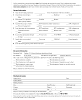
You'll be entered into a quarterly drawing for
free
Cisco Press books by returning this survey! Cisco is dedicated to customer
satisfaction and would like to hear your thoughts on these printed manuals. Please visit the Cisco Product Comments on-line survey at
www.cisco.com/go/crc
to submit your comments about accessing Cisco technical manuals. Thank you for your time.
General Information
1
Years of networking experience:
Years of experience with Cisco products:
2
I have these network types:
LAN
Backbone
WAN
Other:
3
I have these Cisco products:
Switches
Routers
Other (specify models):
4
I perform these types of tasks:
H/W installation and/or maintenance
S/W configuration
Network management
Other:
5
I use these types of documentation:
H/W installation
H/W configuration
S/W configuration
Command reference
Quick reference
Release notes
Online help
Other:
6
I access this information through:
% Cisco.com
% CD-ROM
% Printed manuals
% Other:
7
I prefer this access method:
Cisco.com
CD-ROM
Printed manuals
Other:
8
I use the following three product features the most:
Document Information
Document Title:
Catalyst 3750 Switch Hardware Installation Guide
Part Number:
78-15136-02
S/W Release (if applicable):
<Software Release>
On a scale of 1–5 (5 being the best), please let us know how we rate in the following areas:
The document is complete.
The information is accurate.
The information is well organized.
The information I wanted was easy to find.
The document is written at my
technical level of understanding.
The information I found was useful to my job.
Please comment on our lowest scores:
Mailing Information
Organization
Date
Contact Name
Mailing Address
City
State/Province
Zip/Postal Code
Country
Phone (
)
Extension
E-mail
Fax
(
)
May we contact you further concerning our documentation?
Yes
No
You can also send us your comments by e-mail to
, or by fax to
408-527-8089
.
When mailing this card from outside of the United States, please enclose in an envelope addressed to the location on the back of this card with
the required postage or fax to 1-408-527-8089.