Cisco WS-C3750X-24T-L Hardware Installation Guide - Page 68
Verifying Switch Operation, Connecting a PC or Terminal to the Console Port
 |
View all Cisco WS-C3750X-24T-L manuals
Add to My Manuals
Save this manual to your list of manuals |
Page 68 highlights
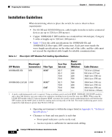
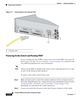
Preparing for Installation Chapter 3 Switch Installation - Six Phillips flat-head screws for attaching the brackets to the switch (Catalyst 3750-24TS, 3750G-24T, and 3750-48TS switches) - Four Phillips machine screws for attaching the brackets to a rack - One cable guide and one black Phillips machine screw for attaching the cable guide to one of the mounting brackets - One redundant power system (RPS) connector cover (for wall mounting) - Two Phillips pan-head screws (for attaching the RPS cover) - Four Phillips truss-head screws (for wall-mounting brackets) - StackWise cable: 0.5-meter, 1-meter, or 3-meter cable. Note If you don't specify the length of the StackWise cable, the 0.5-meter cable is supplied by default. Verifying Switch Operation Before installing the switch in a rack, on a wall, or on a table or shelf, you should power the switch and verify that the switch passes POST. These sections describe the steps required to connect a PC to the switch console port, and to power on the switch and observe POST: • Connecting a PC or Terminal to the Console Port, page 3-8 • Powering On the Switch and Running POST, page 3-10 Connecting a PC or Terminal to the Console Port To connect a PC to the console port, use the supplied RJ-45-to-DB-9 adapter cable. To connect the switch console port to a terminal, you need to provide a RJ-45-to-DB-25 female DTE adapter. You can order a kit (part number ACS-DSBUASYN=) containing that adapter from Cisco. For console port and adapter pinout information, see the "Cable and Adapter Specifications" section on page B-6. The terminal-emulation software-frequently a PC application such as Hyperterminal or Procomm Plus-makes communication between the switch and your PC or terminal possible. Catalyst 3750 Switch Hardware Installation Guide 3-8 78-15136-02
-
 1
1 -
2
-
3
-
4
-
5
-
6
-
7
-
8
-
9
-
10
-
11
-
12
-
13
-
14
-
15
-
16
-
17
-
18
-
19
-
20
-
21
-
22
-
23
-
24
-
25
-
26
-
27
-
28
-
29
-
30
-
31
-
32
-
33
-
34
-
35
-
36
-
37
-
38
-
39
-
40
-
41
-
42
-
43
-
44
-
45
-
46
-
47
-
48
-
49
-
50
-
51
-
52
-
53
-
54
-
55
-
56
-
57
-
58
-
59
-
60
-
61
-
62
-
 63
63 -
 64
64 -
 65
65 -
 66
66 -
 67
67 -
 68
68 -
 69
69 -
 70
70 -
 71
71 -
 72
72 -
 73
73 -
74
-
75
-
76
-
77
-
78
-
79
-
80
-
81
-
82
-
83
-
84
-
85
-
86
-
87
-
88
-
89
-
90
-
91
-
92
-
93
-
94
-
95
-
96
-
97
-
98
-
99
-
100
-
101
-
102
-
103
-
104
-
105
-
106
-
107
-
108
-
109
-
110
-
111
-
112
-
113
-
114
-
115
-
116
-
117
-
118
-
119
-
120
-
121
-
122
-
123
-
124
-
125
-
126
-
127
-
128
-
129
-
130
-
131
-
132
-
133
-
134
-
135
-
136
-
137
-
138
-
139
-
140
-
141
-
142
-
143
-
144
-
145
-
146
-
147
-
148
-
149
-
150
-
151
-
152
-
153
-
154
-
155
-
156
-
157
-
158
-
159
-
160
-
161
-
162
-
163
-
164
-
165
-
166
-
167
-
168
-
169
-
170
-
171
-
172
-
173
-
174
-
175
-
176
-
177
-
178
-
179
-
180
-
181
-
182
-
183
-
184
-
185
-
186
-
187
-
188
-
189
-
190
-
191
-
192
-
193
-
194
-
195
-
196
-
197
-
198
 |
 |