Cisco WS-C3750X-24T-L Hardware Installation Guide - Page 50
Master LED, Port LEDs and Modes, Port Mode, Description
 |
View all Cisco WS-C3750X-24T-L manuals
Add to My Manuals
Save this manual to your list of manuals |
Page 50 highlights
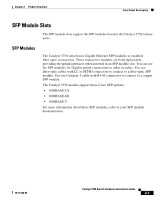
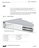
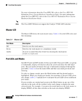
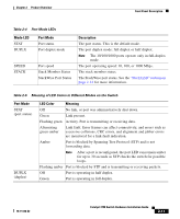
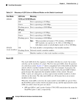
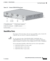
Front Panel Description Chapter 2 Product Overview For more information about the Cisco RPS 300, refer to the Cisco RPS 300 Redundant Power System Hardware Installation Guide. For more information about the Cisco RPS 675, refer to the Cisco RPS 675 Redundant Power System Hardware Installation Guide. Note The Cisco RPS 300 does not support the Catalyst 3750G-24TS switches. Master LED The Master LED shows the stack master status. Table 2-2 lists the LED colors and their meanings. Table 2-3 Master LED Port Mode Off Green Amber Description Switch is not the stack master. Switch is the stack master or a standalone switch. An error occurred when the switch was selecting the stack master switch or a stack error. Port LEDs and Modes Each RJ-45 port and SFP module slot has a port LED. These port LEDs, as a group or individually, display information about the switch and about the individual ports. The port modes determine the type of information displayed through the port LEDs. Table 2-4 lists the mode LEDs and their associated port mode and meaning. To select or change a mode, press the Mode button until the desired mode is highlighted. When you change port modes, the meanings of the port LED colors also change. Table 2-5 explains how to interpret the port LED colors in different port modes. If your switches are stacked and you press the Mode button on any one of the switches in the stack, all the switches in the stack change to display the same selected mode. For example, if you press the mode button on the stack master to display SPEED, all the other switches in the stack also display SPEED. 2-10 Catalyst 3750 Switch Hardware Installation Guide 78-15136-02
-
 1
1 -
2
-
3
-
4
-
5
-
6
-
7
-
8
-
9
-
10
-
11
-
12
-
13
-
14
-
15
-
16
-
17
-
18
-
19
-
20
-
21
-
22
-
23
-
24
-
25
-
26
-
27
-
28
-
29
-
30
-
31
-
32
-
33
-
34
-
35
-
36
-
37
-
38
-
39
-
40
-
41
-
42
-
43
-
44
-
 45
45 -
 46
46 -
 47
47 -
 48
48 -
 49
49 -
 50
50 -
 51
51 -
 52
52 -
 53
53 -
 54
54 -
 55
55 -
56
-
57
-
58
-
59
-
60
-
61
-
62
-
63
-
64
-
65
-
66
-
67
-
68
-
69
-
70
-
71
-
72
-
73
-
74
-
75
-
76
-
77
-
78
-
79
-
80
-
81
-
82
-
83
-
84
-
85
-
86
-
87
-
88
-
89
-
90
-
91
-
92
-
93
-
94
-
95
-
96
-
97
-
98
-
99
-
100
-
101
-
102
-
103
-
104
-
105
-
106
-
107
-
108
-
109
-
110
-
111
-
112
-
113
-
114
-
115
-
116
-
117
-
118
-
119
-
120
-
121
-
122
-
123
-
124
-
125
-
126
-
127
-
128
-
129
-
130
-
131
-
132
-
133
-
134
-
135
-
136
-
137
-
138
-
139
-
140
-
141
-
142
-
143
-
144
-
145
-
146
-
147
-
148
-
149
-
150
-
151
-
152
-
153
-
154
-
155
-
156
-
157
-
158
-
159
-
160
-
161
-
162
-
163
-
164
-
165
-
166
-
167
-
168
-
169
-
170
-
171
-
172
-
173
-
174
-
175
-
176
-
177
-
178
-
179
-
180
-
181
-
182
-
183
-
184
-
185
-
186
-
187
-
188
-
189
-
190
-
191
-
192
-
193
-
194
-
195
-
196
-
197
-
198
 |
 |