Cisco WS-C3750X-24T-L Hardware Installation Guide - Page 156
Optional Con Simple Network Management Protocol SNMP by, Step 5
 |
View all Cisco WS-C3750X-24T-L manuals
Add to My Manuals
Save this manual to your list of manuals |
Page 156 highlights
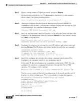
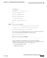
Entering the Initial Configuration Information Appendix D Quick Setup By Using the CLI-Based Setup Program D-12 Step 5 Enter a virtual terminal (Telnet) password, and press Return. The password can be from 1 to 25 alphanumeric characters, is case sensitive, allows spaces, but ignores leading spaces. Enter virtual terminal password: terminal-password Step 6 (Optional) Configure Simple Network Management Protocol (SNMP) by responding to the prompts. You can also configure SNMP later through the CLI or CMS interface. To configure SNMP later type no. Configure SNMP Network Management? [no]: no Step 7 Enter the interface name (physical interface or VLAN name) of the interface that connects to the management network, and press Return. For this release, always use vlan1 as that interface. Enter interface name used to connect to the management network from the above interface summary: vlan1 Step 8 Configure the interface by entering the switch IP address and subnet mask and pressing Return. The IP address and subnet masks shown below are examples. Configuring interface vlan1: Configure IP on this interface? [yes]: yes IP address for this interface: 10.4.120.106 Subnet mask for this interface [255.0.0.0]: 255.0.0.0 Step 9 Enter Y to configure the switch as the cluster command switch. Enter N to configure it as a member switch or as a standalone switch. If you enter N, the switch appears as a candidate switch in the CMS. You can configure the switch as a command switch later through the CLI or CMS interface. To configure it later type no. Would you like to enable as a cluster command switch? [yes/no]: no You have now completed the initial configuration of the switch and the switch displays its initial configuration. This is an example of output that appears: The following configuration command script was created: hostname switch1 enable secret 5 $1$Ulq8$DlA/OiaEbl90WcBPd9cOn1 enable password enable_password line vty 0 15 password terminal-password no snmp-server ! no ip routing Catalyst 3750 Switch Hardware Installation Guide 78-15136-02
-
 1
1 -
2
-
3
-
4
-
5
-
6
-
7
-
8
-
9
-
10
-
11
-
12
-
13
-
14
-
15
-
16
-
17
-
18
-
19
-
20
-
21
-
22
-
23
-
24
-
25
-
26
-
27
-
28
-
29
-
30
-
31
-
32
-
33
-
34
-
35
-
36
-
37
-
38
-
39
-
40
-
41
-
42
-
43
-
44
-
45
-
46
-
47
-
48
-
49
-
50
-
51
-
52
-
53
-
54
-
55
-
56
-
57
-
58
-
59
-
60
-
61
-
62
-
63
-
64
-
65
-
66
-
67
-
68
-
69
-
70
-
71
-
72
-
73
-
74
-
75
-
76
-
77
-
78
-
79
-
80
-
81
-
82
-
83
-
84
-
85
-
86
-
87
-
88
-
89
-
90
-
91
-
92
-
93
-
94
-
95
-
96
-
97
-
98
-
99
-
100
-
101
-
102
-
103
-
104
-
105
-
106
-
107
-
108
-
109
-
110
-
111
-
112
-
113
-
114
-
115
-
116
-
117
-
118
-
119
-
120
-
121
-
122
-
123
-
124
-
125
-
126
-
127
-
128
-
129
-
130
-
131
-
132
-
133
-
134
-
135
-
136
-
137
-
138
-
139
-
140
-
141
-
142
-
143
-
144
-
145
-
146
-
147
-
148
-
149
-
150
-
 151
151 -
 152
152 -
 153
153 -
 154
154 -
 155
155 -
 156
156 -
 157
157 -
 158
158 -
 159
159 -
 160
160 -
 161
161 -
162
-
163
-
164
-
165
-
166
-
167
-
168
-
169
-
170
-
171
-
172
-
173
-
174
-
175
-
176
-
177
-
178
-
179
-
180
-
181
-
182
-
183
-
184
-
185
-
186
-
187
-
188
-
189
-
190
-
191
-
192
-
193
-
194
-
195
-
196
-
197
-
198
 |
 |
