D-Link DES-3028 Product Manual - Page 132
w Rapid Spanning Tree, Port Transition States, STP Bridge Global Settings
 |
UPC - 790069305375
View all D-Link DES-3028 manuals
Add to My Manuals
Save this manual to your list of manuals |
Page 132 highlights
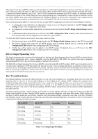
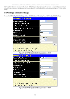
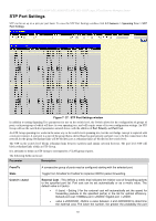
DES-3028 DES-3028P DES-3028G DES-3052 DES-3052P Layer 2 Fast Ethernet Managed Switch This protocol will also tag BPDU packets so receiving devices can distinguish spanning tree instances, spanning tree regions and the VLANs associated with them. An MSTI ID will classify these instances. MSTP will connect multiple spanning trees with a Common and Internal Spanning Tree (CIST). The CIST will automatically determine each MSTP region, its maximum possible extent and will appear as one virtual bridge that runs a single spanning tree. Consequentially, frames assigned to different VLANs will follow different data routes within administratively established regions on the network, continuing to allow simple and full processing of frames, regardless of administrative errors in defining VLANs and their respective spanning trees. Each switch utilizing the MSTP on a network will have a single MSTP configuration that will have the following three attributes: 1. A configuration name defined by an alphanumeric string of up to 32 characters (defined in the STP Bridge Global Settings window in the Configuration Name field). 2. A configuration revision number (named here as a Revision Level and found in the STP Bridge Global Settings window) and; 3. A 4096-element table (defined here as a VID List in the MST Configuration Table window), which will associate each of the possible 4096, VLANs supported by the Switch for a given instance. To utilize the MSTP function on the Switch, three steps need to be taken: 1. The Switch must be set to the MSTP setting (found in the STP Bridge Global Settings window in the STP Version field) 2. The correct spanning tree priority for the MSTP instance must be entered (defined here as a Priority in the MST Configuration Table window when configuring an MSTI ID settings). 3. VLANs that will be shared must be added to the MSTP Instance ID (defined here as a VID List in the MST Configuration Table window when configuring an MSTI ID settings). 802.1w Rapid Spanning Tree The Switch implements two versions of the Spanning Tree Protocol, the Rapid Spanning Tree Protocol (RSTP) as defined by the IEEE 802.1w specification and a version compatible with the IEEE 802.1d STP. RSTP can operate with legacy equipment implementing IEEE 802.1d, however the advantages of using RSTP will be lost. The IEEE 802.1w Rapid Spanning Tree Protocol (RSTP) evolved from the 802.1d STP standard. RSTP was developed in order to overcome some limitations of STP that impede the function of some recent switching innovations, in particular, certain Layer 3 functions that are increasingly handled by Ethernet switches. The basic function and much of the terminology is the same as STP. Most of the settings configured for STP are also used for RSTP. This section introduces some new Spanning Tree concepts and illustrates the main differences between the two protocols. Port Transition States An essential difference between the three protocols is in the way ports transition to a forwarding state and in the way this transition relates to the role of the port (forwarding or not forwarding) in the topology. RSTP combines the transition states disabled, blocking and listening used in 802.1d and creates a single state Discarding. In either case, ports do not forward packets. In the STP port transition states disabled, blocking or listening or in the RSTP port state discarding, there is no functional difference, the port is not active in the network topology. Table 6-2 below compares how the two protocols differ regarding the port state transition. All three protocols calculate a stable topology in the same way. Every segment will have a single path to the root bridge. All bridges listen for BPDU packets. However, BPDU packets are sent more frequently - with every Hello packet. BPDU packets are sent even if a BPDU packet was not received. Therefore, each link between bridges is sensitive to the status of the link. Ultimately this difference results in faster detection of failed links, and thus faster topology adjustment. A drawback of 802.1d is this absence of immediate feedback from adjacent bridges. 802.1w RSTP 802.1d STP Forwarding Learning Discarding Disabled No No Discarding Blocking No No Discarding Listening No No Learning Learning No Yes Forwarding Forwarding Yes Yes Table 7- 2. Comparing Port States 118
-
 1
1 -
2
-
3
-
4
-
5
-
6
-
7
-
8
-
9
-
10
-
11
-
12
-
13
-
14
-
15
-
16
-
17
-
18
-
19
-
20
-
21
-
22
-
23
-
24
-
25
-
26
-
27
-
28
-
29
-
30
-
31
-
32
-
33
-
34
-
35
-
36
-
37
-
38
-
39
-
40
-
41
-
42
-
43
-
44
-
45
-
46
-
47
-
48
-
49
-
50
-
51
-
52
-
53
-
54
-
55
-
56
-
57
-
58
-
59
-
60
-
61
-
62
-
63
-
64
-
65
-
66
-
67
-
68
-
69
-
70
-
71
-
72
-
73
-
74
-
75
-
76
-
77
-
78
-
79
-
80
-
81
-
82
-
83
-
84
-
85
-
86
-
87
-
88
-
89
-
90
-
91
-
92
-
93
-
94
-
95
-
96
-
97
-
98
-
99
-
100
-
101
-
102
-
103
-
104
-
105
-
106
-
107
-
108
-
109
-
110
-
111
-
112
-
113
-
114
-
115
-
116
-
117
-
118
-
119
-
120
-
121
-
122
-
123
-
124
-
125
-
126
-
 127
127 -
 128
128 -
 129
129 -
 130
130 -
 131
131 -
 132
132 -
 133
133 -
 134
134 -
 135
135 -
 136
136 -
 137
137 -
138
-
139
-
140
-
141
-
142
-
143
-
144
-
145
-
146
-
147
-
148
-
149
-
150
-
151
-
152
-
153
-
154
-
155
-
156
-
157
-
158
-
159
-
160
-
161
-
162
-
163
-
164
-
165
-
166
-
167
-
168
-
169
-
170
-
171
-
172
-
173
-
174
-
175
-
176
-
177
-
178
-
179
-
180
-
181
-
182
-
183
-
184
-
185
-
186
-
187
-
188
-
189
-
190
-
191
-
192
-
193
-
194
-
195
-
196
-
197
-
198
-
199
-
200
-
201
-
202
-
203
-
204
-
205
-
206
-
207
-
208
-
209
-
210
-
211
-
212
-
213
-
214
-
215
-
216
-
217
-
218
-
219
-
220
-
221
-
222
-
223
-
224
-
225
-
226
-
227
-
228
-
229
-
230
-
231
-
232
-
233
-
234
-
235
-
236
-
237
-
238
-
239
-
240
-
241
-
242
-
243
-
244
-
245
-
246
-
247
-
248
-
249
-
250
-
251
-
252
-
253
-
254
-
255
-
256
-
257
-
258
-
259
-
260
-
261
-
262
-
263
-
264
-
265
-
266
-
267
-
268
-
269
-
270
-
271
-
272
-
273
-
274
-
275
-
276
-
277
-
278
-
279
-
280
-
281
-
282
-
283
-
284
-
285
-
286
-
287
-
288
-
289
-
290
-
291
-
292
-
293
-
294
-
295
-
296
-
297
-
298
-
299
-
300
-
301
-
302
-
303
-
304
-
305
-
306
-
307
-
308
-
309
-
310
-
311
-
312
-
313
-
314
-
315
-
316
-
317
-
318
-
319
-
320
-
321
-
322
-
323
-
324
-
325
-
326
-
327
-
328
-
329
-
330
-
331
-
332
-
333
 |
 |