D-Link DES-3028 Product Manual - Page 201
IP-MAC-Port Binding, IMP Global Settings - d link cli manual
 |
UPC - 790069305375
View all D-Link DES-3028 manuals
Add to My Manuals
Save this manual to your list of manuals |
Page 201 highlights
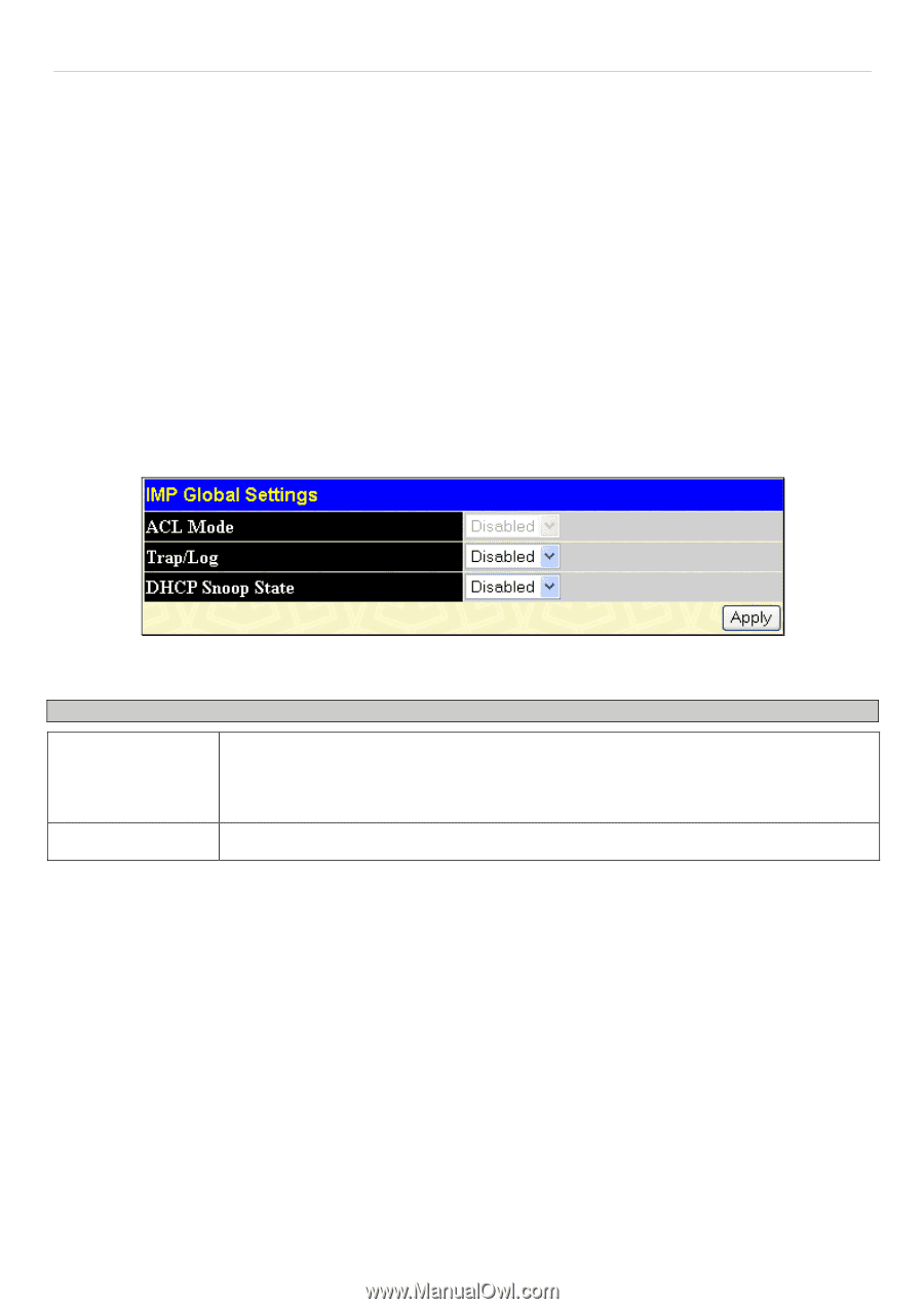
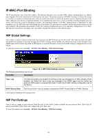
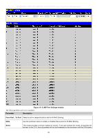
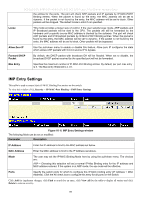
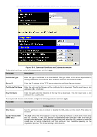
DES-3028 DES-3028P DES-3028G DES-3052 DES-3052P Layer 2 Fast Ethernet Managed Switch IP-MAC-Port Binding The IP network layer uses a four-byte address. The Ethernet link layer uses a six-byte MAC address. Binding these two address types together allows the transmission of data between the layers. The primary purpose of IP-MAC binding is to restrict the access to a switch to a number of authorized users. Only the authorized client can access the Switch's port by checking the pair of IPMAC addresses with the pre-configured database. If an unauthorized user tries to access an IP-MAC binding enabled port, the system will block the access by dropping its packet. The maximum number of IP-MAC binding entries is dependant on chip capability (e.g. the ARP table size) and storage size of the device. For this series of switches, Active and inactive entries use the same database. The maximum entry number is 500. The creation of authorized users can be manually configured by CLI or Web. The function is port-based, meaning a user can enable or disable the function on the individual port. IMP Global Settings This window is used to enable or disable the Trap Log State and DHCP Snoop state on the switch. The Trap/Log field will enable and disable the sending of trap log messages for IP-MAC binding. When enabled, the Switch will send a trap message to the SNMP agent and the Switch log when an ARP packet is received that doesn't match the IP-MAC binding configuration set on the Switch. To view this window click, Security > IP-MAC-Port Binding > IMP Global Settings Figure 10- 4. IMP Global Settings window The following parameters can be set: Parameter Description Trap / Log This field will enable and disable the sending of trap log messages for IP-MAC binding. When enabled, the Switch will send a trap log message to the SNMP agent and the Switch log when an ARP packet is received that doesn't match the IP-MAC binding configuration set on the Switch. DHCP Snoop State Use the pull-down menu to enable or disable the DHCP Snoop State for IP-MAC Binding. Click Apply to implement the settings made. IMP Port Settings Select a port or a range of ports with the From Port and To Port fields. Enable or disable the port with the State, Allow Zero IP and Forward DHCP packet field, and configure the port's Max entry. To view this window click, Security > IP-MAC-Port Binding > IMP Port Settings 187
-
 1
1 -
2
-
3
-
4
-
5
-
6
-
7
-
8
-
9
-
10
-
11
-
12
-
13
-
14
-
15
-
16
-
17
-
18
-
19
-
20
-
21
-
22
-
23
-
24
-
25
-
26
-
27
-
28
-
29
-
30
-
31
-
32
-
33
-
34
-
35
-
36
-
37
-
38
-
39
-
40
-
41
-
42
-
43
-
44
-
45
-
46
-
47
-
48
-
49
-
50
-
51
-
52
-
53
-
54
-
55
-
56
-
57
-
58
-
59
-
60
-
61
-
62
-
63
-
64
-
65
-
66
-
67
-
68
-
69
-
70
-
71
-
72
-
73
-
74
-
75
-
76
-
77
-
78
-
79
-
80
-
81
-
82
-
83
-
84
-
85
-
86
-
87
-
88
-
89
-
90
-
91
-
92
-
93
-
94
-
95
-
96
-
97
-
98
-
99
-
100
-
101
-
102
-
103
-
104
-
105
-
106
-
107
-
108
-
109
-
110
-
111
-
112
-
113
-
114
-
115
-
116
-
117
-
118
-
119
-
120
-
121
-
122
-
123
-
124
-
125
-
126
-
127
-
128
-
129
-
130
-
131
-
132
-
133
-
134
-
135
-
136
-
137
-
138
-
139
-
140
-
141
-
142
-
143
-
144
-
145
-
146
-
147
-
148
-
149
-
150
-
151
-
152
-
153
-
154
-
155
-
156
-
157
-
158
-
159
-
160
-
161
-
162
-
163
-
164
-
165
-
166
-
167
-
168
-
169
-
170
-
171
-
172
-
173
-
174
-
175
-
176
-
177
-
178
-
179
-
180
-
181
-
182
-
183
-
184
-
185
-
186
-
187
-
188
-
189
-
190
-
191
-
192
-
193
-
194
-
195
-
 196
196 -
 197
197 -
 198
198 -
 199
199 -
 200
200 -
 201
201 -
 202
202 -
 203
203 -
 204
204 -
 205
205 -
 206
206 -
207
-
208
-
209
-
210
-
211
-
212
-
213
-
214
-
215
-
216
-
217
-
218
-
219
-
220
-
221
-
222
-
223
-
224
-
225
-
226
-
227
-
228
-
229
-
230
-
231
-
232
-
233
-
234
-
235
-
236
-
237
-
238
-
239
-
240
-
241
-
242
-
243
-
244
-
245
-
246
-
247
-
248
-
249
-
250
-
251
-
252
-
253
-
254
-
255
-
256
-
257
-
258
-
259
-
260
-
261
-
262
-
263
-
264
-
265
-
266
-
267
-
268
-
269
-
270
-
271
-
272
-
273
-
274
-
275
-
276
-
277
-
278
-
279
-
280
-
281
-
282
-
283
-
284
-
285
-
286
-
287
-
288
-
289
-
290
-
291
-
292
-
293
-
294
-
295
-
296
-
297
-
298
-
299
-
300
-
301
-
302
-
303
-
304
-
305
-
306
-
307
-
308
-
309
-
310
-
311
-
312
-
313
-
314
-
315
-
316
-
317
-
318
-
319
-
320
-
321
-
322
-
323
-
324
-
325
-
326
-
327
-
328
-
329
-
330
-
331
-
332
-
333
 |
 |