D-Link DES-3028 Product Manual - Page 158
Understanding CoS, An Example of the Default CoS Mapping on the Switch
 |
UPC - 790069305375
View all D-Link DES-3028 manuals
Add to My Manuals
Save this manual to your list of manuals |
Page 158 highlights
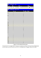
DES-3028 DES-3028P DES-3028G DES-3052 DES-3052P Layer 2 Fast Ethernet Managed Switch Figure 8- 1. An Example of the Default CoS Mapping on the Switch The picture above shows the default priority setting for the Switch. Class-3 has the highest priority of the four priority classes of service on the Switch. In order to implement CoS, the user is required to instruct the Switch to examine the header of a packet to see if it has the proper identifying tag. Then the user may forward these tagged packets to designated classes of service on the Switch where they will be emptied, based on priority. For example, lets say a user wishes to have a video conference between two remotely set computers. On the receiving end, the administrator instructs the Switch to examine packets for this tag, acquires the tagged packets and maps them to a class queue on the Switch. Then in turn, the administrator will set a priority for this queue so that will be emptied before any other packet is forwarded. This results in the end user receiving all packets sent as quickly as possible, thus prioritizing the queue and allowing for an uninterrupted stream of packets, which optimizes the use of bandwidth available for the video conference. Understanding CoS The Switch has four priority classes of service. These priority classes of service are labeled as 3, the high class to 0, the lowest class. The eight priority tags, specified in IEEE 802.1p are mapped to the Switch's priority classes of service as follows: Priority 0 is assigned to the Switch's Q1 class. Priority 1 is assigned to the Switch's Q0 class. Priority 2 is assigned to the Switch's Q0 class. Priority 3 is assigned to the Switch's Q1 class. Priority 4 is assigned to the Switch's Q2 class. Priority 5 is assigned to the Switch's Q2 class. Priority 6 is assigned to the Switch's Q3 class. Priority 7 is assigned to the Switch's Q3 class. For strict priority-based scheduling, any packets residing in the higher priority classes of service are transmitted first. Multiple strict priority classes of service are emptied based on their priority tags. Only when these classes are empty, are packets of lower priority transmitted. 144
-
 1
1 -
2
-
3
-
4
-
5
-
6
-
7
-
8
-
9
-
10
-
11
-
12
-
13
-
14
-
15
-
16
-
17
-
18
-
19
-
20
-
21
-
22
-
23
-
24
-
25
-
26
-
27
-
28
-
29
-
30
-
31
-
32
-
33
-
34
-
35
-
36
-
37
-
38
-
39
-
40
-
41
-
42
-
43
-
44
-
45
-
46
-
47
-
48
-
49
-
50
-
51
-
52
-
53
-
54
-
55
-
56
-
57
-
58
-
59
-
60
-
61
-
62
-
63
-
64
-
65
-
66
-
67
-
68
-
69
-
70
-
71
-
72
-
73
-
74
-
75
-
76
-
77
-
78
-
79
-
80
-
81
-
82
-
83
-
84
-
85
-
86
-
87
-
88
-
89
-
90
-
91
-
92
-
93
-
94
-
95
-
96
-
97
-
98
-
99
-
100
-
101
-
102
-
103
-
104
-
105
-
106
-
107
-
108
-
109
-
110
-
111
-
112
-
113
-
114
-
115
-
116
-
117
-
118
-
119
-
120
-
121
-
122
-
123
-
124
-
125
-
126
-
127
-
128
-
129
-
130
-
131
-
132
-
133
-
134
-
135
-
136
-
137
-
138
-
139
-
140
-
141
-
142
-
143
-
144
-
145
-
146
-
147
-
148
-
149
-
150
-
151
-
152
-
 153
153 -
 154
154 -
 155
155 -
 156
156 -
 157
157 -
 158
158 -
 159
159 -
 160
160 -
 161
161 -
 162
162 -
 163
163 -
164
-
165
-
166
-
167
-
168
-
169
-
170
-
171
-
172
-
173
-
174
-
175
-
176
-
177
-
178
-
179
-
180
-
181
-
182
-
183
-
184
-
185
-
186
-
187
-
188
-
189
-
190
-
191
-
192
-
193
-
194
-
195
-
196
-
197
-
198
-
199
-
200
-
201
-
202
-
203
-
204
-
205
-
206
-
207
-
208
-
209
-
210
-
211
-
212
-
213
-
214
-
215
-
216
-
217
-
218
-
219
-
220
-
221
-
222
-
223
-
224
-
225
-
226
-
227
-
228
-
229
-
230
-
231
-
232
-
233
-
234
-
235
-
236
-
237
-
238
-
239
-
240
-
241
-
242
-
243
-
244
-
245
-
246
-
247
-
248
-
249
-
250
-
251
-
252
-
253
-
254
-
255
-
256
-
257
-
258
-
259
-
260
-
261
-
262
-
263
-
264
-
265
-
266
-
267
-
268
-
269
-
270
-
271
-
272
-
273
-
274
-
275
-
276
-
277
-
278
-
279
-
280
-
281
-
282
-
283
-
284
-
285
-
286
-
287
-
288
-
289
-
290
-
291
-
292
-
293
-
294
-
295
-
296
-
297
-
298
-
299
-
300
-
301
-
302
-
303
-
304
-
305
-
306
-
307
-
308
-
309
-
310
-
311
-
312
-
313
-
314
-
315
-
316
-
317
-
318
-
319
-
320
-
321
-
322
-
323
-
324
-
325
-
326
-
327
-
328
-
329
-
330
-
331
-
332
-
333
 |
 |
