D-Link DES-3028 Product Manual - Page 20
Rear Panel Description, Side panels of the DES-3028G/DES-3028/DES-3052 - des switch
 |
UPC - 790069305375
View all D-Link DES-3028 manuals
Add to My Manuals
Save this manual to your list of manuals |
Page 20 highlights
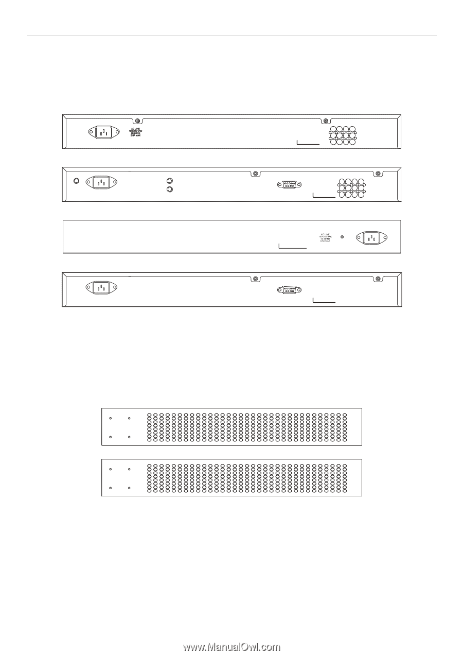
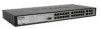
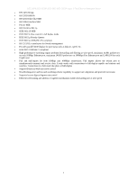
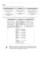
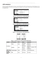
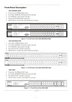
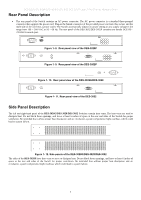
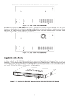
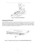
DES-3028 DES-3028P DES-3028G DES-3052 DES-3052P Layer 2 Fast Ethernet Managed Switch Rear Panel Description The rear panel of the Switch contains an AC power connector. The AC power connector is a standard three-pronged connector that supports the power cord. Plug-in the female connector of the provided power cord into this socket, and the male side of the cord into a power outlet. The Switch automatically adjusts its power setting to any supply voltage in the range from 100 ~ 240 VAC at 50 ~ 60 Hz. The rear panel of the DES-3052/DES-3052P contains one female DCE RS 232 DB-9 console port. Figure 1- 8. Rear panel view of the DES-3028P AC LINE 100-240 VAC 50-60 Hz 5A MAX Console Figure 1- 9. Rear panel view of the DES-3052P Figure 1- 10. Rear panel view of the DES-3028G/DES-3028 AC LINE 100-240 VAC 50-60 Hz 0.5A MAX Console Figure 1- 11. Rear panel view of the DES-3052 Side Panel Description The left and right-hand panel of the DES-3028G/DES-3028/DES-3052 Switches contain heat vents. The heat vents are used to dissipate heat. Do not block these openings, and leave at least 6 inches of space at the rear and sides of the Switch for proper ventilation. Be reminded that without proper heat dissipation and air circulation, system components might overheat, which could lead to system failure. Figure 1- 12. Side panels of the DES-3028G/DES-3028/DES-3052 The sides of the DES-3028P have heat vents to serve to dissipate heat. Do not block these openings, and leave at least 6 inches of space at the rear and sides of the Switch for proper ventilation. Be reminded that without proper heat dissipation and air circulation, system components might overheat, which could lead to system failure. 6
-
 1
1 -
2
-
3
-
4
-
5
-
6
-
7
-
8
-
9
-
10
-
11
-
12
-
13
-
14
-
 15
15 -
 16
16 -
 17
17 -
 18
18 -
 19
19 -
 20
20 -
 21
21 -
 22
22 -
 23
23 -
 24
24 -
 25
25 -
26
-
27
-
28
-
29
-
30
-
31
-
32
-
33
-
34
-
35
-
36
-
37
-
38
-
39
-
40
-
41
-
42
-
43
-
44
-
45
-
46
-
47
-
48
-
49
-
50
-
51
-
52
-
53
-
54
-
55
-
56
-
57
-
58
-
59
-
60
-
61
-
62
-
63
-
64
-
65
-
66
-
67
-
68
-
69
-
70
-
71
-
72
-
73
-
74
-
75
-
76
-
77
-
78
-
79
-
80
-
81
-
82
-
83
-
84
-
85
-
86
-
87
-
88
-
89
-
90
-
91
-
92
-
93
-
94
-
95
-
96
-
97
-
98
-
99
-
100
-
101
-
102
-
103
-
104
-
105
-
106
-
107
-
108
-
109
-
110
-
111
-
112
-
113
-
114
-
115
-
116
-
117
-
118
-
119
-
120
-
121
-
122
-
123
-
124
-
125
-
126
-
127
-
128
-
129
-
130
-
131
-
132
-
133
-
134
-
135
-
136
-
137
-
138
-
139
-
140
-
141
-
142
-
143
-
144
-
145
-
146
-
147
-
148
-
149
-
150
-
151
-
152
-
153
-
154
-
155
-
156
-
157
-
158
-
159
-
160
-
161
-
162
-
163
-
164
-
165
-
166
-
167
-
168
-
169
-
170
-
171
-
172
-
173
-
174
-
175
-
176
-
177
-
178
-
179
-
180
-
181
-
182
-
183
-
184
-
185
-
186
-
187
-
188
-
189
-
190
-
191
-
192
-
193
-
194
-
195
-
196
-
197
-
198
-
199
-
200
-
201
-
202
-
203
-
204
-
205
-
206
-
207
-
208
-
209
-
210
-
211
-
212
-
213
-
214
-
215
-
216
-
217
-
218
-
219
-
220
-
221
-
222
-
223
-
224
-
225
-
226
-
227
-
228
-
229
-
230
-
231
-
232
-
233
-
234
-
235
-
236
-
237
-
238
-
239
-
240
-
241
-
242
-
243
-
244
-
245
-
246
-
247
-
248
-
249
-
250
-
251
-
252
-
253
-
254
-
255
-
256
-
257
-
258
-
259
-
260
-
261
-
262
-
263
-
264
-
265
-
266
-
267
-
268
-
269
-
270
-
271
-
272
-
273
-
274
-
275
-
276
-
277
-
278
-
279
-
280
-
281
-
282
-
283
-
284
-
285
-
286
-
287
-
288
-
289
-
290
-
291
-
292
-
293
-
294
-
295
-
296
-
297
-
298
-
299
-
300
-
301
-
302
-
303
-
304
-
305
-
306
-
307
-
308
-
309
-
310
-
311
-
312
-
313
-
314
-
315
-
316
-
317
-
318
-
319
-
320
-
321
-
322
-
323
-
324
-
325
-
326
-
327
-
328
-
329
-
330
-
331
-
332
-
333
 |
 |