D-Link DES-3028 Product Manual - Page 133
Edge Port, P2P Port, 802.1D/802.1w/802.1s Compatibility, STP LoopBack Prevention - d link manual
 |
UPC - 790069305375
View all D-Link DES-3028 manuals
Add to My Manuals
Save this manual to your list of manuals |
Page 133 highlights
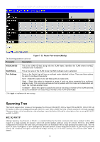
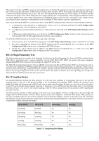
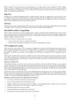
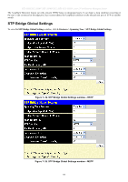
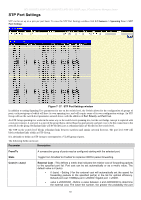
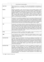
DES-3028 DES-3028P DES-3028G DES-3052 DES-3052P Layer 2 Fast Ethernet Managed Switch RSTP is capable of a more rapid transition to a forwarding state - it no longer relies on timer configurations - RSTP compliant bridges are sensitive to feedback from other RSTP compliant bridge links. Ports do not need to wait for the topology to stabilize before transitioning to a forwarding state. In order to allow this rapid transition, the protocol introduces two new variables: the edge port and the point-to-point (P2P) port. Edge Port The edge port is a configurable designation used for a port that is directly connected to a segment where a loop cannot be created. An example would be a port connected directly to a single workstation. Ports that are designated as edge ports transition to a forwarding state immediately without going through the listening and learning states. An edge port loses its status if it receives a BPDU packet, immediately becoming a normal spanning tree port. P2P Port A P2P port is also capable of rapid transition. P2P ports may be used to connect to other bridges. Under RSTP, all ports operating in full-duplex mode are considered to be P2P ports, unless manually overridden through configuration. 802.1D/802.1w/802.1s Compatibility MSTP or RSTP can interoperate with legacy equipment and is capable of automatically adjusting BPDU packets to 802.1d format when necessary. However, any segment using 802.1d STP will not benefit from the rapid transition and rapid topology change detection of MSTP or RSTP. The protocol also provides for a variable used for migration in the event that legacy equipment on a segment is updated to use RSTP or MSTP. The Spanning Tree Protocol (STP) operates on two levels: 1. On the switch level, the settings are globally implemented. 2. On the port level, the settings are implemented on a per user-defined group of ports basis. STP LoopBack Prevention When connected to other switches, STP is an important configuration in consistency for delivering packets to ports and can greatly improve the throughput of your switch. Yet, even this function can malfunction with the emergence of STP BPDU packets that occasionally loopback to the Switch, such as BPDU packets looped back from an unmanaged switch connected to the DES-3028P. To maintain the consistency of the throughput, the DES-3028P now implements the STP LoopBack prevention function. When the STP LoopBack Detection function is enabled, the Switch will be protected against a loop occurring between switches. Once a BPDU packet returns to the Switch, this function will detect that there is an anomaly occurring and will place the receiving port in an error-disabled state. Consequentially, a message will be placed in the Switch's Syslog and will be defined there as "BPDU Loop Back on Port #". Setting the LoopBack Timer The LoopBack timer plays a key role in the next step the switch will take to resolve this problem. Choosing a non-zero value on the timer will enable the Auto-Recovery Mechanism. When the timer expires, the Switch will again look for its returning BPDU packet on the same port. If no returning packet is received, the Switch will recover the port as a Designated Port in the Discarding State. If another returning BPDU packet is received, the port will remain in a blocked state, the timer will reset to the specified value, restart, and the process will begin again. For those who choose not to employ this function, the LoopBack Recovery time must be set to zero. In this case, when a BPDU packet is returned to the Switch, the port will be placed in a blocking state and a message will be sent to the Syslog of the switch. To recover the port, the administrator must disable the state of the problematic port and enable it again. This is the only method available to recover the port when the LoopBack Recover Time is set to 0. Regulations and Restrictions for the LoopBack Detection Function All versions of STP (STP and RSTP) can enable this feature. May be configured globally (STP Global Bridge Settings). Neighbor switches of the Switch must have the capability to forward BPDU packets. Switches the fail to meet this requirement will disable this function for the port in question on the Switch. The default setting for this function is disabled. The default setting for the LoopBack timer is 60 seconds. This setting will only be operational if the interface is STP-enabled. 119
-
 1
1 -
2
-
3
-
4
-
5
-
6
-
7
-
8
-
9
-
10
-
11
-
12
-
13
-
14
-
15
-
16
-
17
-
18
-
19
-
20
-
21
-
22
-
23
-
24
-
25
-
26
-
27
-
28
-
29
-
30
-
31
-
32
-
33
-
34
-
35
-
36
-
37
-
38
-
39
-
40
-
41
-
42
-
43
-
44
-
45
-
46
-
47
-
48
-
49
-
50
-
51
-
52
-
53
-
54
-
55
-
56
-
57
-
58
-
59
-
60
-
61
-
62
-
63
-
64
-
65
-
66
-
67
-
68
-
69
-
70
-
71
-
72
-
73
-
74
-
75
-
76
-
77
-
78
-
79
-
80
-
81
-
82
-
83
-
84
-
85
-
86
-
87
-
88
-
89
-
90
-
91
-
92
-
93
-
94
-
95
-
96
-
97
-
98
-
99
-
100
-
101
-
102
-
103
-
104
-
105
-
106
-
107
-
108
-
109
-
110
-
111
-
112
-
113
-
114
-
115
-
116
-
117
-
118
-
119
-
120
-
121
-
122
-
123
-
124
-
125
-
126
-
127
-
 128
128 -
 129
129 -
 130
130 -
 131
131 -
 132
132 -
 133
133 -
 134
134 -
 135
135 -
 136
136 -
 137
137 -
 138
138 -
139
-
140
-
141
-
142
-
143
-
144
-
145
-
146
-
147
-
148
-
149
-
150
-
151
-
152
-
153
-
154
-
155
-
156
-
157
-
158
-
159
-
160
-
161
-
162
-
163
-
164
-
165
-
166
-
167
-
168
-
169
-
170
-
171
-
172
-
173
-
174
-
175
-
176
-
177
-
178
-
179
-
180
-
181
-
182
-
183
-
184
-
185
-
186
-
187
-
188
-
189
-
190
-
191
-
192
-
193
-
194
-
195
-
196
-
197
-
198
-
199
-
200
-
201
-
202
-
203
-
204
-
205
-
206
-
207
-
208
-
209
-
210
-
211
-
212
-
213
-
214
-
215
-
216
-
217
-
218
-
219
-
220
-
221
-
222
-
223
-
224
-
225
-
226
-
227
-
228
-
229
-
230
-
231
-
232
-
233
-
234
-
235
-
236
-
237
-
238
-
239
-
240
-
241
-
242
-
243
-
244
-
245
-
246
-
247
-
248
-
249
-
250
-
251
-
252
-
253
-
254
-
255
-
256
-
257
-
258
-
259
-
260
-
261
-
262
-
263
-
264
-
265
-
266
-
267
-
268
-
269
-
270
-
271
-
272
-
273
-
274
-
275
-
276
-
277
-
278
-
279
-
280
-
281
-
282
-
283
-
284
-
285
-
286
-
287
-
288
-
289
-
290
-
291
-
292
-
293
-
294
-
295
-
296
-
297
-
298
-
299
-
300
-
301
-
302
-
303
-
304
-
305
-
306
-
307
-
308
-
309
-
310
-
311
-
312
-
313
-
314
-
315
-
316
-
317
-
318
-
319
-
320
-
321
-
322
-
323
-
324
-
325
-
326
-
327
-
328
-
329
-
330
-
331
-
332
-
333
 |
 |